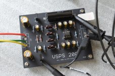
vsps200m passes the usual tests with no issues
the Z-reg works properly with no ripple detected in the output or on the voltage rails
(The measurement sensitivity is not as high as with the phonoclone measurements earlier, this is just a open bench test, but the absence of 120 Hz ripple as was seen with the phonoclone 4 can be confirmed)
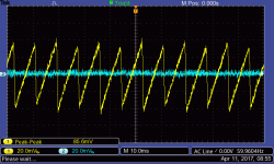
scope trace screencap shows V-- in yellow with the expected 80 mV p-p ripple and clean V- in blue.
the Z-reg works properly with no ripple detected in the output or on the voltage rails
(The measurement sensitivity is not as high as with the phonoclone measurements earlier, this is just a open bench test, but the absence of 120 Hz ripple as was seen with the phonoclone 4 can be confirmed)
scope trace screencap shows V-- in yellow with the expected 80 mV p-p ripple and clean V- in blue.
Attachments
Last edited:
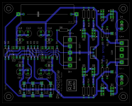
continuing my Quixotic quest for a better phonoclone 4 layout...
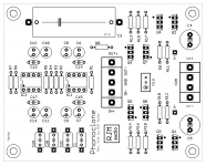
4.4b brings all the signal traces to the bottom, all protected by a ground plane.
I had to reduce the trace width to fit everything under the IC however.
4.4b brings all the signal traces to the bottom, all protected by a ground plane.
I had to reduce the trace width to fit everything under the IC however.
Attachments
Last edited:
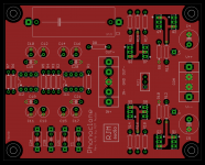
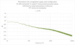
Phonoclone 4.4s
"s" denotes an out-of-series, once-off version. This is basically a big vanity project / moonshot / experiment to see if the board layout has any influence on the ripple component in the output signal.
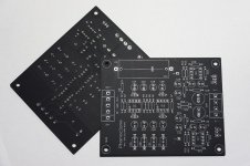
I got 10 boards made at pcbway for all of $21 shipped so not a huge investment on my part. Crazy I know... it's actually cheaper to order 10 pcs twice than 20 pcs at once which doesn't make a whole lot of sense to me but whatever they feel works for them I guess. Quality somewhat behind e.g. the usual black ones like the PC3.8a above but for prototypes or for personal-use projects like this it's great!
"s" denotes an out-of-series, once-off version. This is basically a big vanity project / moonshot / experiment to see if the board layout has any influence on the ripple component in the output signal.
I got 10 boards made at pcbway for all of $21 shipped so not a huge investment on my part. Crazy I know... it's actually cheaper to order 10 pcs twice than 20 pcs at once which doesn't make a whole lot of sense to me but whatever they feel works for them I guess. Quality somewhat behind e.g. the usual black ones like the PC3.8a above but for prototypes or for personal-use projects like this it's great!
Attachments
Last edited:
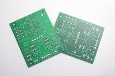
Moonshot - achieved! 
I don't what was wrong with the 4.0b layout, but whatever was wrong there was righted on phonoclone 4.4s. I guess I got careless... somewhere. Being 100% rigorous on the ground connection order and keeping the power rails located as far away from sensitive signal traces paid off at any rate.
I have 4 sets of 4.4s prototypes left which I will send to the people who ordered 4.0b from me. If there are any unclaimed they will be available to anyone curious.
Attachments

I posted all the 4.4s boards today, to earsandeyes, rsritchey and a couple of other people. The Phonoclone 4 will continue however as 4.5b with the 70x90 mounting holes. Details attached. (its barely changed from 4.4, mounting holes moved and some parts got renumbered...)
My 4.4s does not sound very different, if at all, from the 4.0b build, which in itself very near to the CrystalFET. It might seem weird that the JFET stage and the IC circuit should sound similar, but remember they have pretty much identical shunt-source voltage regulation so that might likely have something to do with it. Maybe the CrystalFET is smoother and rounder, the phonoclone 4 a tad more dynamic, but its anyways close.
Compared to the Phonoclone 3 the 4 sounds quieter and more deliberate. Less sparkly and more solid. I prefer it, personally, as I like that lower midrange weight. Others might prefer an emphasis elsewhere.
Attachments

PhonoClone 3.5h again
Thanks Richard,
Got a nice surprise in the post today! A 4.4s Limited Edition
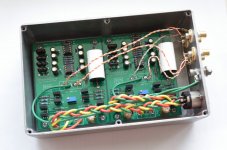
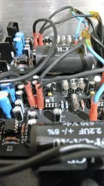
Just recently finished a second 3.5h using LCR capacitors for C1,2 and 3, also tried the IC2 with AD797's, image seemed a bit indistinct to me, so return the OPA27 and things fell back into place. Only my view of course and may have been due to build issues etc.
Not much, if any difference but preferred the original.
I had thought I was finished 'messing about' .....
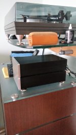
Attached are pictures of the second build - soon to be decommissioned!
Thanks Richard,
Got a nice surprise in the post today! A 4.4s Limited Edition
Just recently finished a second 3.5h using LCR capacitors for C1,2 and 3, also tried the IC2 with AD797's, image seemed a bit indistinct to me, so return the OPA27 and things fell back into place. Only my view of course and may have been due to build issues etc.
Not much, if any difference but preferred the original.
I had thought I was finished 'messing about'
.....Attached are pictures of the second build - soon to be decommissioned!
Attachments
Not much, if any difference but preferred the original.
It's good to experiment like that with two similar builds, it gives you a better idea of what works and what doesn't, what does what, and something of how much range the circuit is capable of.
Now when you go build the 4.4s it should be a lot easier to lock on to what the power supply changes are bringing to the table.
Dear rjm,
I just want to say thanks for posting the limited edition Phonoclone 4.4s to me. I received the boards in the mail today. It looks and feel very high quality. Can't wait to put it together and compare head on with my DIY built Pearl 2 phono. It will be an interesting match!
Thanks again,
Tom
I just want to say thanks for posting the limited edition Phonoclone 4.4s to me. I received the boards in the mail today. It looks and feel very high quality. Can't wait to put it together and compare head on with my DIY built Pearl 2 phono. It will be an interesting match!
Thanks again,
Tom
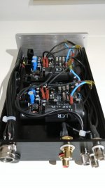
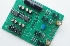
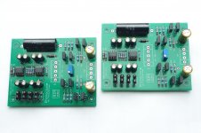
When complete they should look something like this:
(please take care to notice the electrolytics are flipped 180 degrees with the negative terminal pointing notional "up")
(please take care to notice the electrolytics are flipped 180 degrees with the negative terminal pointing notional "up")
Attachments
Last edited:
Richard, always reading this thread. I see modifications in the Phonoclone.
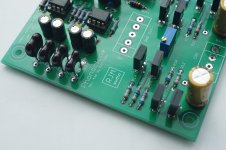
I have the VSPS 300 dual mono. Looking at this last plate of the Phonoclone, I see that it has ceramic capacitors in decoupling of VCC and VEE. The vsps does not have it.
Can these capacitors be added to the VSPS 300?
I have the VSPS 300 dual mono. Looking at this last plate of the Phonoclone, I see that it has ceramic capacitors in decoupling of VCC and VEE. The vsps does not have it.
Can these capacitors be added to the VSPS 300?
Since I asked one question, I do another one. I'm interested in the CrystalFET preamplifier.
But I have an old turntable, Aiwa Ap2400 from 1982.
To use an MC cartridge is a modern turntable required ?.
There is much improvement in the sound of the CrystalFET with respect to VSPS 300 with MM ?.
Greetings.
But I have an old turntable, Aiwa Ap2400 from 1982.
To use an MC cartridge is a modern turntable required ?.
There is much improvement in the sound of the CrystalFET with respect to VSPS 300 with MM ?.
Greetings.
Hi Jose,
A cheap MC cart would cost you much more than your Aiwa deck is worth. The money would be better spent, I think, buying a better turntable instead but you can use an MC cart with it if you want.
You can add ceramic capacitors to the VSPS300 board by soldering across the leads of the 100 uF electrolytics underneath the board, or between pin 1 and 7 of the op amp socket.
While I haven't compared VSPS300 to CrystalFET, its not like one was designed to be better or more "high end" than the other, think of them as two very different circuits with similar level of quality and performance.
Richard
Phonoclone output
Dear All,
I have been a DL103 lover but I gave up at some point because I never found a phonostage for it. This project is tempting... so I might give it a try!
The problem for me is to figure out what's the optimal connection with the rest of the chain. And I'd like some feedback from you guys.
The DL103 has a 0.3mv output which means that setting the phonoclone at 75dB gain I should get almost 2Vrms output which is more than enough, but the problem is how to control the volume... a topic which always bugged me!
I see two alternatives:
1. Phonoclone at 75dB ---> Volume Pot (which rating?) -- > Nelson Pass B1buffer --> amplifier. My concern here is whether bass output will be smashing, whenever I tried to eliminate a line stage, I always felt the lack of bass!
2. Phonoclone set to a lower 65dB --> low (12dB) gain tube line stage with volume control. My concearn here is whether I need a buffer between phonoclone and line stage.
What do you think guys?
Pierre
I would set the phono to around 60-63dB
In my experience, the kabusa calculator gives decent suggestions, although I tend to like a bit more gain
https://www.kabusa.com/pregain.htm
The gain that you need on your pre is a matter of how loud you usually listen to music, and how sensitive your amp is.
There is nice article here in diyaudio that explains gain structure nicely. I do not have the link right now, but if you google "diyaudio gain structure" it should come up.
The B1 article on FW site also gives some nice insight on what should work and what not.
About the pot, I think the suggested value for B1 is 10-20K
To get more bass I found that changing the output cap to 10uF made a significant improvement.
About the buffer before the line, it is not required. The line stage IS your buffer.
If you are thinking to add it before the pot, then theoretically it is not required.
If it makes some difference, it would be a matter of how much improvement you will get from the much better load to the phono, and how much you will lose from the extra stage.
- Home
- Source & Line
- Analogue Source
- The Phonoclone and VSPS PCB Help Desk