are the spikes at 60Hz, 120, 240, 360Hz etc?What are the frequencies of the spikes?
The odd harmonics are usually dominant, but if I read that correctly you don't have odd harmonics, only evens.
Well, I've done some testing since yesterday. The noise in the stereo (single-board) VSPS is definitely NOT hum; it is RFI, specifically FM radio stations, of which there are many nearby. I went ahead and added .01uF ceramics across the inputs of each jack, then added 220pF styrene caps across pins 2&3 and 5&6 on the 5532 chip.
After trying numerous orientations, I have found a spot in my system where the boxes aren't too near to other power cables, etc. The VSPS, for whatever reason, is highly sensitive to RFI. Even with the filters in place, it's still audible, albeit at levels well beyond where I would ever listen.
I am using a moving coil cartridge and a step-up (+20dB) transformer. Perhaps this is complicating the RFI pick-up issue, though I have used the same set-up before with no problems. After reading through some earlier suggestions, I am thinking about deploying some little ferrite beads as well.
The VSPS has no "anti RFI" features at all, it's up to the end user to take additional measures in proportion to the severity of the environment.
I heard that it's the bipolar transistors of the op amp input section that demux the radio signals back into the audio spectrum and that JFETs do not have this attribute. So you might want to try a JFET input op amp like OPA2134 instead of the NE5532.
All cables, including the power umbilical, should be shielded. If you haven't already you should use an RFI filter at the AC input to the power supply. In general, it's worth noting that RFI can sneak in just as easily though the power cable as the input cable, so best to not concentrate efforts exclusively on the input section. Indeed that various capacitors across the input did not solve the problem suggests rather that it's power supply related.
Yay, fixed my hum issue. The LED in the power switch borrowed power from the diode bridge output (the ~+12V side). Probably something with the switch itself but it was feeding back into the circuit. removing that connection cleaned it up a ton.
Now my LED is powered off of the mains with a simple series 50Kohm resistor and a diode (parallel reverse polarity).
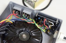
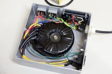
ahhh, finally. I knew it had to be something stupid too. A few pics of it buttoned up. I wanted to laser etch the faces like I did my integrated amp project, but ran out of time lol.
Anyway, thanks for all the input guys.


Now my LED is powered off of the mains with a simple series 50Kohm resistor and a diode (parallel reverse polarity).
ahhh, finally. I knew it had to be something stupid too. A few pics of it buttoned up. I wanted to laser etch the faces like I did my integrated amp project, but ran out of time lol.
Anyway, thanks for all the input guys.
This is my now-regulated power supply. Output is +11V -11V courtesy of a single Z-Reg board.
@Erik I'd still be somewhat concerned as hanging a diode off the V++ to COM should really not have caused interference like that... I don't have a lot of experience on that though since I never bother with LEDs!
@Erik I'd still be somewhat concerned as hanging a diode off the V++ to COM should really not have caused interference like that... I don't have a lot of experience on that though since I never bother with LEDs!
Attachments
Last edited:
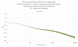
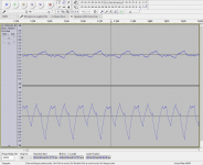
Well, that worked nicely. Fronting the S-Reg with a Z-Reg-equipped power supply eliminates all ripple and hum from the phonoclone output.
So the final report is that the noise was interference from charging currents flowing in the S-Reg being picked up by the phonoclone input section. It was not a ground loop or a board error per se., more that the the S-Reg is not a good choice for the application - not by itself at any rate. It does not handle the input ripple gracefully like a series circuit would.
And since as a project these have always been single board solutions the phonoclone 4 - while it will work fine with a regulated power supply - is being withdrawn. If you would like a set I have a few left, let me know. I will not be ordering more.
(That is one spectacularly clean FFT though... mmm mm.)
Attachments
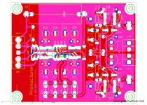
My recent work on the phonoclone 4 has been folded back into a new version of the phonoclone 3 (3.8a) which is directly based off the 4.2 layout but with the X-Reg in place of the S-Reg.
3.8a has some considerable improvements in the phonoclone layout (fingers crossed... ) and the X-Reg has also been completely redone. The BOM has been tweaked so the X-Reg uses standard resistor values now instead of those oddball 75k and 30k values.
I have sent 3.8a out for fabrication, as well as VSPS200m and Sapphire 4.1m.
3.8a has some considerable improvements in the phonoclone layout (fingers crossed...
) and the X-Reg has also been completely redone. The BOM has been tweaked so the X-Reg uses standard resistor values now instead of those oddball 75k and 30k values.I have sent 3.8a out for fabrication, as well as VSPS200m and Sapphire 4.1m.
Attachments
The vsps200 is a simpler, updated Z-Reg version of the vsps300. The X-Reg based vsps300 is still available for now.
http://www.diyaudio.com/forums/blogs/rjm/1413-very-simple-phono-stage-vsps200-20th-anniversary-mono-edition.html
http://www.diyaudio.com/forums/blogs/rjm/1413-very-simple-phono-stage-vsps200-20th-anniversary-mono-edition.html
Ah yes, just had a look at it on your website. I liked the idea of the on-board buffer on the VSPSX though, but again, you can always insert a separate b-board, as I did with my stereo VSPS.
Also, I noticed the title for the VSPS200 section in your board page: it should say "with Z-reg" instead of "with X-reg"!
Also, I noticed the title for the VSPS200 section in your board page: it should say "with Z-reg" instead of "with X-reg"!
No takers? I'll go first then:
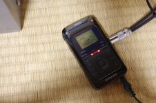
1. The Kenwood recorder gives an authentic representation of the tonality of the analog chain, with very little loss of overall quality.
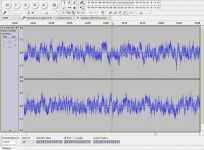
2. I've back-and-forth compared this a couple of dozen times and can barely sense any difference between the two power supplies. Which is to say I cannot hear anything I could attribute to the ripple noise visible in the FFT spectrum.
3. While I have no confidence I could pick this out blind, I do feel that there is a small difference: the unregulated supply sounds more open and dynamic, the Z-Reg version flatter and closed in. So I'd have to say I'd prefer the unregulated supply. This might be do to the distribution of filter capacitance, which now has 1000 uF both in the supply and the phono stage. I'll be tweaking that next.
note the files are 16 bit 48kHz wav. They don't seem to play in the browser but work fine for me if I download them and open with VLC or media player.
1. The Kenwood recorder gives an authentic representation of the tonality of the analog chain, with very little loss of overall quality.
2. I've back-and-forth compared this a couple of dozen times and can barely sense any difference between the two power supplies. Which is to say I cannot hear anything I could attribute to the ripple noise visible in the FFT spectrum.
3. While I have no confidence I could pick this out blind, I do feel that there is a small difference: the unregulated supply sounds more open and dynamic, the Z-Reg version flatter and closed in. So I'd have to say I'd prefer the unregulated supply. This might be do to the distribution of filter capacitance, which now has 1000 uF both in the supply and the phono stage. I'll be tweaking that next.
note the files are 16 bit 48kHz wav. They don't seem to play in the browser but work fine for me if I download them and open with VLC or media player.
I didn't comment because I didn't hear any difference - but I could only play through the audio jack on decent but not high-end headphones. I may try my 32/384 USB DAC but I don't expect much difference there either. With tinnitus it's really only bigger differences that I can make out.
I think you didn't hear any difference because there isn't any difference to hear. I was a bit surprised ... I was expecting more blackness, or more resolution, or more low level details ... but I guess the power supply has passed over the threshold were it not longer limits what you hear. There is no more there to unlock.
The only thing I could possibly pick out is a bit of "too much capacitance" disease starting to creep in. I've ripped out all the capacitance now between the Z-Reg output and Z-Reg input (100 uF, 1000 uF, and 0.1 uF caps removed) so there is just 1000 uF at the Z-Reg input and the 4x 100 uF, 0.1 uF near the op amps. We'll give that a try a walk it back up if necessary. [Neither regulator uses feedback control, so there is no need to have capacitance on the input and output for stability..]
The only thing I could possibly pick out is a bit of "too much capacitance" disease starting to creep in. I've ripped out all the capacitance now between the Z-Reg output and Z-Reg input (100 uF, 1000 uF, and 0.1 uF caps removed) so there is just 1000 uF at the Z-Reg input and the 4x 100 uF, 0.1 uF near the op amps. We'll give that a try a walk it back up if necessary. [Neither regulator uses feedback control, so there is no need to have capacitance on the input and output for stability..]
Removing all the caps between Z-Reg and S-Reg does give things a more lightfooted, dynamic presentation. I like it. Unfortunately there's some weird low level hum again, which varies randomly in intensity.
Whatever "it" is, I bet its the same gremlin that's responsible for all the trouble so far. I just don't know where it lives.
Whatever "it" is, I bet its the same gremlin that's responsible for all the trouble so far. I just don't know where it lives.
Attachments
- Home
- Source & Line
- Analogue Source
- The Phonoclone and VSPS PCB Help Desk