really liked the movie China Syndrome.
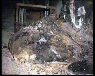
Alas the infamous "elephants foot" fuel lava under the Chernobyl reactor...... Nasty stuff!
Mark
Attachments
Zero Cool said:Actually, I was at a surplus store in Florida a few years back that had a GIANT knife switch. i mean this thing had to be at least 36" long and 24" wide and had a geared handle mechanisim that would spin up a flywheel system that would slam the contacts closed and latched once the handle got all the way down. really cool device!
ZIIIIPPPP CLACK!
I think i sat there for at least 15 minutes playing with the thing. i should have bought it but it was expensive and HEAVY and i was leaving on a plane in a few hours. would have made a KILLER movie prop. I wish i would could have at least taken a photo of the thing. never seen another one like it. I mean it was BIG!
Maybe that should be my next project, duplicate that thing....
Zc
Ok now you guys got me thinking about this thing again. If anyone find any photo's of something like this, please let me know.
This thing wasnt actually a knife switch if i remember correctly, it was just a large handle/gear/flywheel driven switch, with DPDT contacts and BIG round contacts, Each one was at least 2-3" in diameter.
I dont remember all of the working details. But there was a large handle that operated a gear driven flywheel, when the handle reached the full posistion, it quickly kicked out a sort of a dogged clutch mechanism that engaged a shaft that moved the contacts. once the contacts had closed fully, the remaining flywheel action was used to ratchet the contacts tight.
Pulling the handle back at that point, released the latch and pulled back the clutch and started the flywheel moving in the other direction with the proccess repeating to move the contacts to the other side.
It made a very distinctive noise zzzzZZZZZPPPPPPPP CLACK! ztztzttztzttztzttttt.
DANG i wish i had bought that thing.
Zc
Monster
I guess the monster will be a lot bigger than this amp (posted on on post 2778 of the Krell Clone thread)?
OK, its the biggest amp I've ever seen.
I guess the monster will be a lot bigger than this amp (posted on on post 2778 of the Krell Clone thread)?
OK, its the biggest amp I've ever seen.

Banned
Joined 2002
Re: Monster
Wonder if it has wheels ?
lgreen said:I guess the monster will be a lot bigger than this amp (posted on on post 2778 of the Krell Clone thread)?
OK, its the biggest amp I've ever seen.
Wonder if it has wheels ?
Okay...a progress report from the hinterlands.
My wife--kind soul that she is--took this past Friday off so as to take over the baby duties so I could get some time in on the Monster front end.
Is it done? No.
But it's pretty well firmed up.
I've got two more things I want to do, but I don't anticipate any problems (famous last words...). Just a little straight-forward engineering.
I had hoped to stick to an isolation transformer and voltage doubler for the power supply. It was going to be rather a tight fit to meet Nelson's specifications with the rail at that level, but I think the path of wisdom is going to be to go with a higher rail after all. The tubes I'm using can take more rail voltage easily, so that won't be a problem.
As I've noted from the beginning, the voltage swing Nelson requested wasn't going to be a problem, but the current...ah, the current...tubes and current aren't exactly the best combination. My first impulse was to use the 6AS7/6080 for the follower output stage. I really, really wanted to make it work. However, the voltage swing and plate dissipation were going to be high enough that I was uncomfortable given the limitations of the tube. This led me to cast about for another candidate.
Bear in mind that I am dead set against using odd tubes, difficult to find tubes, absurdly expensive tubes, or any tube whose manufacture involves palladium, moon dust, or cat gut. That limits things a bit. Even some tubes I thought might be good possibilities are getting scarce.
(Jeez, anyone tried to source a decent 6SL7 recently? Not that it's a good output tube, but I had figured that it would be around for a while. All I saw were "no name" brands, and only a limited selection of those; cheap, yes, but how good are they? How reliable? I hate to say it, but I may have to give up on tubes entirely. This is getting to be a pain for someone with no more resources than I have.)
Anyway, to make a long story short, I have selected an output tube. The circuit seems to be working well on the bench. As soon as I can get another day, perhaps two, I think I can wrap this thing up.
No promises as to when that will happen, though. Might be this coming weekend, might be next year. I'll try to nail it as soon as possible, though, and that's a promise.
Grey
Grey - sounds a little mad, but how about either a 6bm4 if you need a sensitive input, or an EL84 (common, cheap, reliable, still produced...) for a less sensitive input?
It all depends on topology with tubes to get current - either multiple parallel tubes, or a voltage gain stage with a current follower (that could be a transformer...
Just some thoughts...
Owen
longterm tube-head moving to the dark side of smoke and mirrors.....
It all depends on topology with tubes to get current - either multiple parallel tubes, or a voltage gain stage with a current follower (that could be a transformer...
Just some thoughts...
Owen
longterm tube-head moving to the dark side of smoke and mirrors.....
Assuming Mr. Rollins's tube front directly drives the output stage, as i do not see driver devices, what will be the target for the slewrate of the amplifier ?
28 output devices surely need quite a bit of current to give them enough speed ?
Has there ever been a fully balanced hybrid, or "would" this be a novelty ?
Bless to cheap IRF's, building such an output with Lateral's would have been a painfull event.
(try to find a 6SQ7 nowadays)
Thanks for the poking, Casey.
hehe plenty of current...
Driving the beasties is a whole 'nuther ball game, as the input impedance is low, and capacitance is high, and requiring wide bandwidth (so the driver does not limit the amp overall)...
So, a few quick scratchings for 2 possible topologies that don't involve transformers (shame) and came up with the following. I have no ballpark voltages yet (!) and hold no caveats... Neither topology is new, or unique, and can be found on the interweb.
Grounded grid input stage. This acts as the voltage gain stage has a gain of u+1 (or thereabouts). Upside, massive bandwidth (comfortably into the high KHz region), downside, has a low input impedance (around 100 ohms but that should not be a big problem, as the miller capacitance is also very low)
and either
1/ an inverted operated tube (triode article by steve bench on a true SE OTL topology)
2/ standard cathode follower.
Both of these topologies avoid nasty additional circuitry, floating heaters etc, and can be made quiet. They also have good bandwidth (again into the high KHz region), and plenty of current.
A good choice of tube would be 5687 - common, and cheap (with a healthy plate dissipation!), that by using each section for the differential circuit, you'd have a reasonable chance of getting close to balance naturally (in terms of gain and everything else) (i.e. one tube handled the + and - signal for a stage).
A less choice alternative would be a grounded grid cascode, or if the limitations of a transformer (or two, and could be tested using a mains torroid) are accepted, then a simple EL84 Differential topology would do the trick very nicely, with very few parts.
More aimed brainfarts later
Owen
Although there have been a number of tube-front/MOSFET-output amps over the years, to my knowledge none of them have been balanced.
As it stands now, the front end will be direct coupled internally, but capacitor coupled to the output stage. In theory, we could redo the gizmo as a Wiggins circlotron (aka Atma-Sphere) and direct couple all the way through, but that's a whole 'nother project.
Be patient. Rome wasn't built in a day.
Grey
Banned
Joined 2002
GRollins said:Although there have been a number of tube-front/MOSFET-output amps over the years, to my knowledge none of them have been balanced.
Grey
Do you have any schematics for such amps ? I'm interested in building one..
J'
Be patient. Rome wasn't built in a day.
Exactly - thats why I threw a few eggs in, to see if we really can create a gournet omelette...
Patiently waiting ;-)
Owen
GRollins said:but capacitor coupled to the output stage.
You can start looking for loads of large film capacitors now, Casey.

jacco vermeulen said:
You can start looking for loads of large film capacitors now, Casey.
Let me know what values, i have 2 excellent shops here with some nice film caps.
Zc
Film bypasses over the bulk power supply electrolytics are always in order. Electrolytics have lousy high frequency response.
The "secret" to the sound quality I get from my main tube amps isn't the circuitry--which is actually fairly standard--it's the power supply.
And, of course, DC blocking caps should always be film caps. I lean towards polystyrene, but some polypropylenes are very, very good, lacking only that last Nth degree of detail. They are much cheaper and available in larger values. Bypass a decent, fairly low cost polypropylene with a small 'styrene and you're nearly there for a fraction of the cost of a full-blooded polystyrene.
Hint: Mouser has inexpensive 50V polystyrene caps. The values are small, so they won't do as the main cap, but for the price you won't go too far wrong trying a couple for bypasses. Pity they're only 50V--not enough ooomph for this run--but certainly enough for most solid state work.
Grey
Regarding tube/MOSFET amp schematics for commercial stuff, there are schematics for one or more of the old Counterpoint models floating around on the web. The only Counterpoint equipment I sold was all tube. I do not endorse the hybrids, per se, I'm just noting that they're out there if you look hard enough.
Do not...repeat DO NOT build just any old hybrid schematic you find on someone's website. Some of the homebrew hybrids out there will kill your speaker and maybe you in the process. Then, just to add insult to injury, they'll self-destruct.
You have been warned.
If you absolutely must tinker with the primordial ichor of the universe, go over the schematic very carefully. Look particularly carefully at the turn-on characteristics. Turn-off is usually pretty benign for tubes, but turn-on can easily send a 100V pulse through your Gates. Don't say I didn't warn you.
Grey
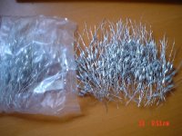
GRollins said:Bypass a decent, fairly low cost polypropylene with a small 'styrene and you're nearly there for a fraction of the cost of a full-blooded polystyrene.
Hear,Hear !
These are 160 volts Siemens polystyrenes(styroflex's)
For some reason overhere these are periodically dumped on the web since a year or so.
Bought this bag of 500 for something like $0.03 the piece.
Siemens(Epcos) used to produce 1% accurate polystyrenes (square orange B31531 series) which were marvellous for RIAA circuits
How's about a nice softstarter for the grid of the tubes ?
Attachments
- Status
- This old topic is closed. If you want to reopen this topic, contact a moderator using the "Report Post" button.
- Home
- Amplifiers
- Pass Labs
- The Pass Monster?