Yeah sorry, but I don't know what could be helpfull in this case. It is a premium kit ordered from linuxguru. I only ordered the power caps and the lm3886 myself.
It should have much smaller DC offsets if it's correctly assembled with authentic parts. Please post pic(s) of the assembled boards as well as the full assembly showing trafo, power wiring, grounding, input wiring, etc.
Hum in the MyRef is almost always due to incorrect shielding/grounding.
From what I can make out the pcb is version 1,4 with the date 01/15/2011.
I used the papers that came with the kit: a list that gave all the supplied components and there place on the pcb and also the picture of the pcb layout.
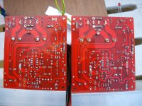
I will try to take pictures of my setup and the pcb top and bottom tomorrow when there is more light.
I used the papers that came with the kit: a list that gave all the supplied components and there place on the pcb and also the picture of the pcb layout.
I will try to take pictures of my setup and the pcb top and bottom tomorrow when there is more light.
So I have taken some pictures, I have also taken some new measurements and I get some strange readings.
The test is done with speaker connected they play music but with a very nasty hum.
The amp with the red input wire moves between 650mV and 715mV on the ouput.
The amp with the black wire and LED goes from 132mV to -132mV while I am measuring.
Hope someone can explane.
The test is done with speaker connected they play music but with a very nasty hum.
The amp with the red input wire moves between 650mV and 715mV on the ouput.
The amp with the black wire and LED goes from 132mV to -132mV while I am measuring.
Hope someone can explane.
Attachments
1.) Power OFF.
2.) disconnect speakers.
3.) build a bulb tester.
4.) short the inputs of the power amps.
5.) power up one channel through the bulb tester.
6.) carefully examine the brightness of the 40W bulb in the bulb tester.
7.) measure the AC voltages at the input to the rectifiers.
8.) measure the DC voltages of the PSU.
9.) measure the AC and DC voltages at the output of the test amp.
10.) report back.
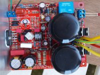
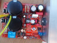
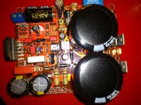
Looks just like mine except for the placement of C7/C23 (Shouldn't matter), and you're missing C34.
I had a on/off thump with the supplied 4.7uf C13, but it went away when I changed it to 2.2uf.
The only time I've had any hum is when I accidentally swapped the input wires.
I had a on/off thump with the supplied 4.7uf C13, but it went away when I changed it to 2.2uf.
The only time I've had any hum is when I accidentally swapped the input wires.
Attachments
Power down. Measure the resistance between the Spkr Return and the Main Audio Ground.
It should not be near zero ohms. Zero ohms, or close to, would indicate a welded relay contact.
Both sides measure at about 4+ ohms.
Today, I hear a only little "pop" during power down. No more buzz, just a harmless little "pop"

I have soldered all the pieces that came with the kit, only C21 is left.
So I did a lightbulb test and with both amplifiers the bulb started bright and then faded in a lightly glowing state.
I measured the DC at R1 and R4 and with both amps the volts where 20.4 V and -20.4 V DC.
At the output there was a difference in both.
The one with the LED gave 3.75 V DC and 7.6 V AC
The amp with no LED gave 0.2 mV to 0.0mV DC sometimes I got a negative(-) sign blinking on the multimeter. The AC was 0.0V
Hope someone can explane.
C34 - 10pF Silver Mica or C0G, is imperative. Without it, the RevC is only marginally stable. However, this may not be the cause of the hum.
You've installed C23 in the place provided for C7, but it shouldn't matter as long as there is no short.
I have soldered all the pieces that came with the kit, only C21 is left.
Oops - then it was probably my omission. Please look around for C34, marked 10pF +/- 0.5 pF (dark brown silver mica). If you can't find it, please pick up a pair of 10pF Silver Mica or C0G ceramic, either from EBay or a regular electronics store, and populate C34.
.
I had a on/off thump with the supplied 4.7uf C13, but it went away when I changed it to 2.2uf.
Mark - your assembly is very tidy, near perfection. Could you give your audible impressions of the Aeon (?) input cap, as well as where it can be sourced at a reasonable price?
Also looks like you've soldered the LM318, which is fine, except that you may find it difficult to roll opamps or the hybrid LF01 module in the future - it's not a show-stopper.
The test is done with speaker connected they play music but with a very nasty hum.
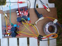
From the first pic, there seems to be multiple ground loops from the toroidal trafo's centre (0V) connector to/from PGND - these are the yellow/green and yellow cables. There's a second ground loop involving the PGND to Earth connection(s), which is optional at any rate and requires the use of a CL60 isolator.
The input cables are unshielded and untwisted for a few cm to the input connector block, and this could pick up some hum (though not what could be described as nasty).
The stereo polar to dual RCA connector shorts the signal grounds at the source end, which might contribute yet another small ground loop involving the shields of the line cable.
From the first pic, there seems to be multiple ground loops from the toroidal trafo's centre (0V) connector to/from PGND - these are the yellow/green and yellow cables. There's a second ground loop involving the PGND to Earth connection(s), which is optional at any rate and requires the use of a CL60 isolator.
How do you propose I connect it all together?
The RCA connectors are still a test setup and will be propperly shielded.
And what is the best option for C34.
For what it's worth, for all my initial auditions of a new build I use that same "Y" setup from either a portable CD player or an iPod with the volume at minimum and then bring it up slowly. If the amp was built correctly there has never been a hum problem. I'm just suggesting the source of the hum is most likely not that "Y" on the source output based on the good results I have had. If all is well with the battery powered source, I then move up to an AC powered unit.
Mark - your assembly is very tidy, near perfection. Could you give your audible impressions of the Aeon (?) input cap, as well as where it can be sourced at a reasonable price?
Also looks like you've soldered the LM318, which is fine, except that you may find it difficult to roll opamps or the hybrid LF01 module in the future - it's not a show-stopper.
Thanks Siva. Those boards deserve 100% effort on the builders part.
The cap was a leftover crossover part from a project I built about 10 years ago. Don't remember where I got them... Can't give a judgement on their performance as the amps are still powering some drivers mounted in cardboard boxes.
Yeah, I decided to solder in the LM318 as I wanted to eliminate unnecessary joints. I've got a cheap SMD rework station and the hot air gun makes it fairly easy to remove parts if necessary.
Last edited:
- Home
- Amplifiers
- Chip Amps
- The new "My Ref" Rev C thread