Stay tuned for a discrete/hybrid module that I've designed called the LF01 - I'll post the schematic, pics and also make the modules/PCBs available shortly.
OK, here's the link to the LF01 announcement - includes the schematic, layout and pic of a prototype (which has been tested and works fine in a Rev C V1.2):
http://www.diyaudio.com/forums/anal...discrete-hybrid-opamp-module.html#post2656217
More details in due course - please post comments related to the LF01 in that thread.
also, are 1/2w resistors too big for signal duties? i found some takman that are only offered in that rating.
0.5w is fine, but you may find it difficult to squeeze them into most locations in the V1.2 PCB. You can try mounting them vertically.
i get fairly loud buzzing from both channels if i turn the amp on without any input connected. when i connect it to my preamp turned on, the noise is reduced humming at woofers that's almost inaudible. preamp powered off, the buzzing resumes. however, when the amp's connected straight to the dac there's only that feint humming even when the dac's off. what's the problem here and could it possibly hurt the sonics?
the amp still buzzes without the interconnects at the inputs
the amp still buzzes without the interconnects at the inputs
Last week I upgraded a Hefler DH-120 power amp by replacing the stock Sangamd 6,600uF caps with two Nippon Chemi-Con 22,000 uF units. The improvement was quite dramatic. So my question - are the caps in the various MyRef BOMs the optimum or is there room for variations there?
To the guys who got uriah's ultimate myref c kit, where is the 'spare' 75k and 47k resistor supposed to go? I can't find the space on the PCB for it.
Also, is it necessary to solder the top portion of the board? I didn't realize there are traces at the top until soldering quite a few large components. Now it's a real problem trying to flow some solder onto the top joints... I messed up and partially fried the outer shell of the panasonic FM cap =\
Also, is it necessary to solder the top portion of the board? I didn't realize there are traces at the top until soldering quite a few large components. Now it's a real problem trying to flow some solder onto the top joints... I messed up and partially fried the outer shell of the panasonic FM cap =\
Maybe you just got a couple extra parts. If the board is filled, I wouldn't worry about it. Make sure the places those parts are supposed to go in are filled with the correct parts!
You do not need to, and in most cases, do not want to, solder to the top of the board. All the holes are plated through, so they already connect with the top of the board. If you just touched the outside of the cap with your hot iron, it will probably still be okay. It wouldn't hurt to buy a new one, though. They cost very little.
I have a comment to make, based on the last few pages of posts. I am glad that others are trying this amp and experimenting with it. However, the last few pages have been filled with "What if I try this...?" and "Can I use that...?" type of questions. This gets very tedious to read, and it's kind of unfair that you're too lazy to read previous pages where much of this is already discussed. Yes, some of us have a lot of experience and we're here to help, but do you expect us to do all your work for you? Then it's not really DIY, is it.
If you want to try something and it hasn't been attempted yet, please go ahead and try it, and then let us know the results. It would be nice to get INPUT from other experimenters instead of endless questions about "How will this sound...?" How do you think this entire endeavor came about? Dario and I and, originally on a much higher level Mauro Penasa and Russ White, decided there was a better way to build an amplifier. We tried stuff. It didn't work. We tried other stuff. It worked a lot better. We came here and told others about it. In case you've never experienced it, it's a wonderful feeling to make a discovery, no matter how insignificant, and help others by telling them about it.
Peace,
Tom E
Last edited:
my apologies, tom. i do realize i been mucking up the thread with trivial posts as of late. but to have gotten the answers by the route of diy, i would have had to spend countless hours and budget- of which neither i have leisure to spare. and what is the joy of discovery but trying out something which hasn't been done before? without asking first i would not have known if that was the case... but excuses aside, i once again apologize if i tested your patience and thank you still for helping me thus far. ")
i've successfully installed 220uf 50v silmic caps for c1 &2 by soldering one of them under the board. the improvement is significant, especially in the bass where it has gained definition and weight. and even the midrange has become more fleshed out without losing out any aspects from when FC's were installed. the caps are so big that it practically overlaps the r2 resistor but since the leads are suppose to be non magnetic i guess i have nothing to worry about(?).
also Dario, was the mills resistor you tried out for r3 a 5w ceramics? installing them in mine has indeed made the sound sweeter but tone is now also a tad bit sharper. still waiting on caddocks...
also Dario, was the mills resistor you tried out for r3 a 5w ceramics? installing them in mine has indeed made the sound sweeter but tone is now also a tad bit sharper. still waiting on caddocks...
i've successfully installed 220uf 50v silmic caps for c1 &2 by soldering one of them under the board. the improvement is significant, especially in the bass where it has gained definition and weight. and even the midrange has become more fleshed out without losing out any aspects from when FC's were installed.
Interesting, in fact I've never tried Silmics in C1/C2 due to dimensions....
Even more interesting I've tried 100uF 63V FCs and surprisingly they sound very very good and almost not harsh, they sound much better than FMs...
I never tried them in the MyRef before because every position I've used them in other projects they were irremediably harsh.
I've ordered 220uF/50V to assess if they can become the new suggested cap for C1/C2.
I've also tried BC038 and they're not good in C1/C2, not bad in C6/C11 but Cerafines are way better.
Talking about C6/C11 now I'm more toward Cerafines... while KZs timbre is fantastic Cerafines are overall much more coherent.
also Dario, was the mills resistor you tried out for r3 a 5w ceramics? installing them in mine has indeed made the sound sweeter but tone is now also a tad bit sharper. still waiting on caddocks...
No, it was not ceramic... see the attached picture
Attachments
......... So my question - are the caps in the various MyRef BOMs the optimum or is there room for variations there?
Sorry, just noticed a typo in a previous post. I was asking specifically about C3 and C8 as part of the PS circuit. Hope I'm reading their function properly. I don't remember any conversation on those components.
Last edited:
The improvement was quite dramatic. So my question - are the caps in the various MyRef BOMs the optimum or is there room for variations there?
Sorry, just noticed a typo in a previous post. I was asking specifically about C3 and C8 as part of the PS circuit. Hope I'm reading their function properly. I don't remember any conversation on those components.
If someone is willing to improve C3/C8 a substantial upgrade are the Mundorf M-Lythic AG (MLPI).
...
The inprovement is general but the two more important parameters improved are a much more balanced timbre and cleanliness of high frequecies.
Hi Bob,
as you can see I've tried different caps for C3/C8:
Nichicon KS 10000uF 50V
Nice and full timbre, bass has not much control, a bit veiled compared to Pannies and Murdorf
Panasonic TS-HA 10000uF 50V
Nice and tight bass, more refined compared to KS but with a bit reverberant and recessed response on medium frequencies.
Mundorf M-Lythic AG (MLPI) 10000uF 63V
Nice and full timbre, more refined and clean compared to both KS and TS-HA, bass is more controlled than TS-HA. Mundorf affirms they've a performance level similar to BlackGates
Other caps to try are Elna LPO and F&T FTCap SI, which should be identical to previous Mundorfs (MLSI) but much cheaper.
I've ordered 220uF/50V to assess if they can become the new suggested cap for C1/C2.
me too. so that i can squeeze them in c9 and compare against BG
thanks for the pic, Dario. having realized I put the wrong buggers in there, I quickly swapped them back and been happier ever since.
has anyone fiddled with higher quality relays? i'd like to try them out but don't know the required parameters. are they just spdt contact and 24vac?
has anyone fiddled with higher quality relays? i'd like to try them out but don't know the required parameters. are they just spdt contact and 24vac?
Higher quality than Omrons?
They already have silver contacts... if you find a better one let us know
PS
Omron G5LE-1-E DC24 has 16A rating Vs. 10A but contact material isn't specified, it could be better? I don't know..
Last edited:
Thanks Dario, I just checked Parts Connexion - $25 each for the Mundorf. I'll have to think a bit on that. Is 10,000uF the only acceptable value?
You can try FTCaps then:
F & T Cap Electrolytic Audio Capacitors
Much cheaper and the core technolgy should be the same (Mundorf are custom made F&T).
The main difference should be that MLPI have copper straight leads while MLSI and F&T SI have steel snap-in terminations.
I can't tell how much performance is affected (for sure the newer are better sounding).
how about introducing 100v caps to c15? nichicon muse is only available in that rating from mouser it seems and since the aesthetic of my boards have already been compromised, i may as well oversize everything. i've already decided to put muse's in c14 under the board.
p.s. this is so much fun. hehe
p.s. this is so much fun. hehe
Last edited:
how about introducing 100v caps to c15?
C15 is part of the speaker protection circuit... why do you want to change it?
can anyone help me with some input/output and transformer wiring questions pretty please?
this is my first amp so i'm not too sure how to wire things up properly. I tried searching for pics of completed my ref c ultimate builds but the wiring arrangement is quite hidden from view. I also tried googling but i think i'm not using the right search terms and the results are irrelevant. I would really appreciate your help please
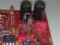
am i supposed to use the supplied pins this way?
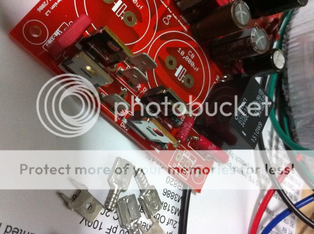
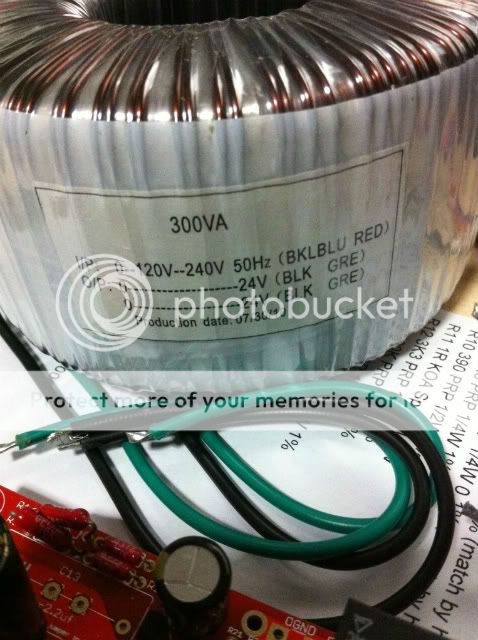
How should i be hooking up my transformer?
As for the IN, am i mistaken that there should only be 2 wires connected there (input and ground)? But why are there 3 solder holes?
About the OUTPUT, there are 3 holes - 2 square pads and one circular. Are the 2 square pads for + (red) and - (black)? What about the circular? I thought it was for the ground but there's another section at the top of the board labelled OGND with the same solder pad configuration as OUT. I'm so sorry for all the stupid questions, i just don't know where to begin searching for help.
this is my first amp so i'm not too sure how to wire things up properly. I tried searching for pics of completed my ref c ultimate builds but the wiring arrangement is quite hidden from view. I also tried googling but i think i'm not using the right search terms and the results are irrelevant. I would really appreciate your help please
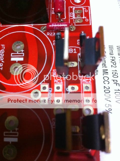
am i supposed to use the supplied pins this way?
An externally hosted image should be here but it was not working when we last tested it.
The connections at the AC1 and AC2 area are confusing for me. I'm not sure what the column of pins in B1 are supposed to be.. and the purpose of so many solder pads.
How should i be hooking up my transformer?
As for the IN, am i mistaken that there should only be 2 wires connected there (input and ground)? But why are there 3 solder holes?
About the OUTPUT, there are 3 holes - 2 square pads and one circular. Are the 2 square pads for + (red) and - (black)? What about the circular? I thought it was for the ground but there's another section at the top of the board labelled OGND with the same solder pad configuration as OUT. I'm so sorry for all the stupid questions, i just don't know where to begin searching for help.
An externally hosted image should be here but it was not working when we last tested it.
Last edited:
C15 is part of the speaker protection circuit... why do you want to change it?
so the higher voltage could bring about an adverse effect?
- Home
- Amplifiers
- Chip Amps
- The new "My Ref" Rev C thread