Some simple diagnostics and a lurking suspicion finally got me to the cause. Sort of embarrassing actually..
Or the optimistic view would be that you DID find it amidst great odds...
Or the optimistic view would be that you DID find it amidst great odds...
That's too kind..
It was actually a really stupid and obvious mistake in retrospect - of course they always are..I'm very happy with the end result though, the music flows in an effortless way - I just listen, no distractions of any sort.
Welcome to swing by for another listen when it suits your schedule..
Well it's been about two weeks since I last posted an update, and am happy to report that things have settled down nicely.
The phono stage is extremely quiet, there is no audible hiss or hum at any sane volume control setting. I'm very pleased overall with the sonic presentation, it images extremely well, and has no particular emphasis on any part of the spectrum.
The 6BD5GT pass tubes in the regulator continue in service with no issues noted since I solved the last problem. (The one of my own doing..)
The phono stage is extremely quiet, there is no audible hiss or hum at any sane volume control setting. I'm very pleased overall with the sonic presentation, it images extremely well, and has no particular emphasis on any part of the spectrum.
The 6BD5GT pass tubes in the regulator continue in service with no issues noted since I solved the last problem. (The one of my own doing..
)
SY says that 60dB above 20mV is 2V. Really?
0.002V x 10^60/20 = 20V
Even with 54dB, it'll be 10V! 54dB IS an insanely high gain after all...
Looks like that finger counting mathematician is missing a few fingers.
Yes, he already figured that out.
My reasoning for the high gain was that my line stage has almost none, and I wanted something approaching the levels typical of CD playback. Eventually I will probably get a set of LL1931 and configure them for 8X as opposed to the 16X of the current LL1941 - I've got a little more gain than I absolutely need with the 300uV Meister Silver.. I figure about 6dB less would be perfect, and I expect the lower gain transformer might offer even more performance - if slightly.
Hey Kevin,
I'm a bit delayed due to a change in spending $$, but I am still planning on getting to this as soon as I can. So...I'm wondering why the PS topology you've chosen. I'm new to pass elements in a PS and wonder why the complexity. Sure seems like regulation is a key point due to NFB, but I'm not clear on ripple rejection of a design like this, and that would seem like a key factor. Can you elaborate? While I have done some reading that suggests at least some ripple rejection I can't seem to make sense of how good it is. (Also seems like the filtration you've used is fairly minimal for the gain involved, but that's coming from someone who has so far only attempted a power amp and a simple linestage). These things make me think the ripple rejection is pretty good. Hmmm.
Thanks,
Carl
PS - relative to the GZ34, I'm wondering if the 6Z4 (which I already have) might work too. I've looked over the data sheets and they seem to meet the basic requirements without going over the limits (that is, 300V, 40mA). Probably there's a good reason to use the GZ34, but I'd love to hear your thoughts on that too.
Last edited:
Hi Carl,
Actually the supply ripple rejection in the phono stage is no more than about 1dB due entirely to the input cascode, all of the ripple killing magic is in the power supply.
The power supply via a combination of passive filtering at the front end, the high internal impedance of the pentode connected pass element (heavily filtered screen supply), and >46dB of feedback in the audio frequency range provides more than 80dB of ripple rejection between the raw supply and the supply output. It also provides a source impedance of an ohm or less at audio frequencies which reduces unintended feedback through the supply to a pretty small value.
I'm not a big fan of RC decoupling networks in low level audio circuitry and tend to avoid them, this makes my designs rather dependent on good power supply quality, but removes an interaction with a potentially poor quality electrolytic and replaces it with a potentially even more problematic interaction with the power supply. I returned to basics for this supply having tried a lot of other things that I liked less well - the origins of this design go all the way back to my first commercial ventures in the late 1980s, it's my oldest, most flexible, and probably best thought out supply design, and has benefited significantly from a design refresh this time around - noise rejection in this design is 20dB better than the previous quietest design. It also reminds that some things suit their purpose well enough that significant improvement is hard to attain.
One area where I can see definite room for improvement would be to replace the reference zener with one based on Morgan Jones' statistical regulator which will be at least 10dB quieter than the current reference - since most of the broadband noise at the output is amplified reference noise this would be a worthwhile improvement.
As it stands this phono pre-amplifier is ridiculously quiet, I worked through the calculations many posts back but I believe that in fact the dominant noise source is the cartridge and SUT combination..
Hey Kevin,
I'm a bit delayed due to a change in spending $$, but I am still planning on getting to this as soon as I can. So...I'm wondering why the PS topology you've chosen. I'm new to pass elements in a PS and wonder why the complexity. Sure seems like regulation is a key point due to NFB, but I'm not clear on ripple rejection of a design like this, and that would seem like a key factor. Can you elaborate? While I have done some reading that suggests at least some ripple rejection I can't seem to make sense of how good it is. (Also seems like the filtration you've used is fairly minimal for the gain involved, but that's coming from someone who has so far only attempted a power amp and a simple linestage). These things make me think the ripple rejection is pretty good. Hmmm.
Thanks,
Carl
PS - relative to the GZ34, I'm wondering if the 6Z4 (which I already have) might work too. I've looked over the data sheets and they seem to meet the basic requirements without going over the limits (that is, 300V, 40mA). Probably there's a good reason to use the GZ34, but I'd love to hear your thoughts on that too.
Umm. OK, per my PS above, I'm forgetting the 400x2 PSU iron, meaning peak voltage is probably 565V, which is a tad too high for a choke loaded 6Z4. Duh...
I would not use a choke input here as the stray magnetic field may be difficult to contain. A single Edcor power transformer provides enough juice for both channels and a raw B+ of slightly over 500V with a single 5AR4 rectifier - both regulators will operate just fine off of the recommended single CLC input filtering. Something you may not be aware of is that the source impedance of the raw supply at low frequencies has a significant impact on the stability of the voltage regulator so I would not stray far from my design intent unless you want to spend a lot of time understanding why it doesn't work correctly.. It's all very carefully thought out and took a lot of debugging to get it to work as intended.
Just a quick update since I've gotten a few questions by email about this design lately.
I listen almost every day to this phono stage and would have to count it as being amongst my best work.
There have been no problems since my last post with the pre or its power supplies. Other system improvements particularly in the line stage highlight just how quiet this design actually is, complementing the performance of my Meister Silver SPU and LL1941 SUTs.. (Run at 16X) For those requiring somewhat less gain I would probably recommend the LL1931 run at 8X.
Note it performs very well with any cartridge I have tried including a vintage Shure with >5mV output and a dcr of over 1K ohm.
Transformers
May I ask, who makes your transformers? I live in U.S.A. also--Chicago really. I have looked several diy phono preamps and I like yours the best as I am a novice diy-er. I am currently building the Krell KSA-100, Jim's Audio clone power amplifier for my european albums I purchased in Germany back in the early 1970s, U.S. Army PX. I like the fact that the tubes are plentiful and cheap!!!Pass tube requires a minimum of 200V for proper operation, it is a series pass after all. I actually get transformers built to spec for most of my designs. Based on ongoing listening experience I still find I prefer this design sonically to some more recent designs. I have not tried the shunt yet..
Hi Spurite,
The plate power transformer was made by Edcor, and I generally buy an off the shelf antek toroid for the filament supplies in my designs.
The plate chokes are Magnequest EXO-001 100H/20mA chokes.
I will post the part numbers for the filament and plate supply transformers soon.
The plate power transformer was made by Edcor, and I generally buy an off the shelf antek toroid for the filament supplies in my designs.
The plate chokes are Magnequest EXO-001 100H/20mA chokes.
I will post the part numbers for the filament and plate supply transformers soon.
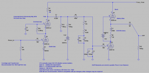
I've received a couple of requests that I post the final schematic as built rather than asking people to take the original and modify it with the various options listed in later posts - so here it is.
Note that I have removed the recommendation for the 6S3P-DR from the latest schematic as the samples I had access to were not nearly as uniform from sample to sample as the 32 6S3P-EV I purchased in several batches.
The chokes (L1 in below schematic) are Magnequest 100H type with a DCR of ~910 - 1000 ohms aka EXO-001, note that the winding resistance is important within the context of this design since the operating point of the upper triode is determined by the voltage impressed between its cold end and the grid. Target current is approximately 10 - 11mA.
Edit 2013-05-12: This is the final version of the audio circuitry.
Attachments
Checking prices of the 6S3P-EV on eBay tonight was interesting - last time I checked they were selling for $1.50 each, these days they seem to be going for between $3 and $7 each depending on quantity, maker, and seller. Still a pretty good bargain compared to the 5842 which is relatively similar in terms of its performance. (They are not exact equivalents)
Audio Chokes
Note that MagneQuest is on Facebook here: https://www.facebook.com/pages/MagneQuest/121507687917410 - should be able to query Mike and probably order the chokes.
Note that the Lundahl LL1668 / 25mA choke with the windings wired in series with a 221 ohm resistor will provide both the required inductance (100H) and proper dc resistance for biasing the choke augmented mu follower second stage.
Edcor HV Transformer And Choke
Power transformer part number is: XPWR228-120
120V 60Hz to 800 volt (400-0-400) @ 100mA,
6.3 volt @ 2A, 6.3 volt @ 1A,
5 volt @ 2A
With Vertical Blue End Bells
Class X Power Transformer
Set up charge has already been covered so the price should be quite reasonable.
Choke P/N is: CXC100-5H-200mA
5H Inductance, 200 mA DC current,
58 ohms DCR with leads, Gapped Core
Hello!
I beg you to read carrefully all what I wrote if your time is forgiving because I have a problem and I am not too good in mathematics so I will be as objective as possible to make you understand what I want to tell.
For quite a while (allmost 1 years of intensive readings all over the net) I am looking for the best possible phono preamp solution only through theoretical and net research and I found some worrying texts on the internet.I thought for a while that a design like FVP5A of allen wright or Toccata with their split riaa "have the touch", only to find later that those who replicated the fvp5a experienced instability with the original values because of the high voltage on some 6922 tube.
I have enough siemens e88cc and others good tube and I bought even some siemens e810f and philips d3a, e282f e280f (etc) too, and now I am troubled about hearing that 6c3p is better in terms of stability or microphonics than d3a...I have only one 6c3p-ev, but I will find the truth.
Now i don't know what to choose between :
1--split riaa a la toccata with battery bias, and all the good stuff ,although 200v dc on a 6922 is a bit too much,
2-- another design prety much as yours with triode strapped e810f and e88cc cascode as front stage, rc riaa and kimmel mu follower with 6j9-pe and 6n6p (or other western combination-I have hundreds of tubes) for the output stage inspired by Patrick Turner and others-you included
and
3-- a lcr design with transformer coupled after the first cascode and kimmel mu-follower final stage.
My question would be, if you are kind to answer to a so much unexperienced designer as myself:
is it possible to couple a 1henry-390 ohms-primary winding dc resistance of a double-c core transformer with 1 square cm and 9 ohms dc secondary dc resistace 13:1 coupling ratio in your cascode anode muscovite design for driving a 600 ohms lcr filter?
I think the reflected impedance in the primary winding would be about 90k ohms.Is it too much for couplind directly as cascode anode load, or better would be to make a cathode follower after cascode with some 12at7 and place the transformer in the cathode?I have two transformers like these from some farmaceutical quipement and they are very well built with multiple screens internal and external and two separate sections for windings.I saw some designs with lundahll anode loads and d3a as pentode and those Lundahlls are 30 henry at only 250 ohms dc resistance which makes me think that my 1 henry 390 ohms dc resistance, 1 square cm surface, double c core will not be too dc current forgiving,
I will first try the rc riaa network to be sure it's worth lcr but can you clarify about my problem?
Why I can't believe it's worth to give lcr a chance as bigger dinamics and ****.I built about to years ago a simple srpp design with 12ax7 and 12at7 like Patrick Turner first preamp and it sounded prety good to y years(a bit dark and resolute sound)in terms of dinamics.Why to bother lcr when I didn't even tried cascode and mu-folllower?
I have the best capacitors and resistors for rc and coupling(silver-mica, mkv siemens, mkp1841 and mmkt1813 ero, low miller styroflex ero and another 100 killos of good passive components so I can experiment.I even built some 30 kilograms power source for 8 different dc rectified and regulated filament rails, simetric and regulated anode voltages between minus-plus 120v dc to 375 v dc and all good stuff for this project.Then the preamplifier chassis is allmost done and contains 7 possible to be used tubes per channel.I just need some theoretical advices from an experienced builder because in my country nobody realised something so extensive in that aria.
- Home
- Source & Line
- Analogue Source
- The "Muscovite" 6S3P Tube Phonostage