In light of further experience I made a minor revision to the value of R6 (see Final PSU) in order to slightly reduce the plate current in the 12AX7 error amplifiers without increasing the loop gain. The value changed from 4.7K to 6.8K and should reduce the plate current to just slightly over 1mA, a slightly better operating point on the plate curves given the relatively low plate voltage across each device. This also reduces screen voltage slightly with a very small resulting reduction in transconductance.
Output noise has dropped very slightly, other changes probably too subtle to pontificate about.
In case it is not obvious the supplies are very much 'in the picture' sonically speaking due to the lack of RC decoupling in this design (a deliberate design choice) but it does mean that significantly altering the performance of the supply and that supply deficits are going to be audible. The PSRR of the cascode input stage is negligible obviously..
Edit: Schematic removed to avoid confusion.
Choice of Input Cap for Filament Regulator
Something to be aware of wrt to the input filter cap in the filament supply is that the ripple current rating should be as high as you can reasonably manage, the input cap in mine is running a case temperature of 20 degrees C over ambient - it's rated at 3.8A ripple current, the load current is 2.5A, and I'm thinking this is getting quite close to the limit.
The part I used is here: ECO-S1CA223CA Panasonic Electronic Components | P6547-ND | DigiKey
I've not really found a better choice in a compact capacitor so I will monitor the situation. It may not be such a bad idea to parallel several 10000uF electrolytics instead. I think a pair of these may be a better choice: UPW1C103MHD Nichicon | 493-1807-ND | DigiKey
- less than half the ESR and the same ripple current rating per cap running at effectively half the current of the hard working cap in my unit.
The point is to choose a cap that will not have to be replaced in a decade or more of use.
Something to be aware of wrt to the input filter cap in the filament supply is that the ripple current rating should be as high as you can reasonably manage, the input cap in mine is running a case temperature of 20 degrees C over ambient - it's rated at 3.8A ripple current, the load current is 2.5A, and I'm thinking this is getting quite close to the limit.
................
The point is to choose a cap that will not have to be replaced in a decade or more of use.
kevinkr,
Have you considered using OS-CON in that particular location? The data sheet of SA series show ripple current of 9.75A for 1000uF/16V !!!
And, by the way, did you know that 6S3P and 6S4P were designed as pair to work in cascode amplifiers? 6S3P for common cathode, 6S4P for common grid. Pinouts of both tubes are different, but so are the interelectrode capacitances. I have a Russian book from 1964 called "Cascode amplifiers" which describes those tubes. (I speak that language a bit).
Best,
Hi Elektroj,
Yes indeed I know about the 6S4P and even thought about using it as the top half in the cascode and choke augmented mu-follower, but went for the 6S3P in all locations as it was simpler and these tubes aren't readily available here in the US.
Oscons are very expensive over here so I did not consider using them, but I will eventually change out the existing cap for a couple of reasonably priced electrolytics that will not have to work as hard. I think the ESR of this cap is a big part of the problem, but truthfully the rise is well within acceptable limits - just that I am a bit uncomfortable with it when it can mostly be eliminated. I think the internal heating will result in shorter life as I do not know how evenly the heating is distributed in the capacitor, but it is operating within ratings..
Line Transients
I made a change to isolate the filament supply from the cathode of the right channel pass tube, believing that this would solve the problem - unfortunately it has not, so I am no closer to understanding the root cause of the problem. Otherwise it is a good idea - it does remove a transient injection path.
Further investigation is required.
Edit: I have removed these older schematics to avoid confusion.
kevinkr, take a look at this book, there might be some hints re. series tubes:
Handbook Preferred Circuits Navy Aeronautical Electronic Equipment : National Bureau of Standards : Free Download & Streaming : Internet Archive
Handbook Preferred Circuits Navy Aeronautical Electronic Equipment : National Bureau of Standards : Free Download & Streaming : Internet Archive
Hi Elektroj,
Thanks for the link, great stuff, some very interesting designs.. I've downloaded it and am reading it, at first blush it does not appear that I have done something egregiously bad, but apparently I have.. LOL
Have a few additional ideas to try tonight, revolving around somewhat input voltage dependent suspected parasitic oscillations in the pass tubes. The problem is not always there, seems to be mostly at times where high line conditions are common. Installed lossier rectifier tube and the problem just went away at least temporarily.
Further investigation required.
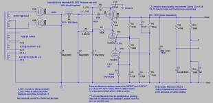
High Voltage PSU Updates 6BD5GT/6V6 (Improved Schematic)
Last night I replaced the 5AR4 with a 6087 which dropped the plate voltage by roughly 20V, the bad behavior stopped immediately and did not recur for the balance of the evening. Since the 20V drop in HV (more than 10% reduction in headroom across the pass element) also slightly reduced the transconductance I surmised that the combination of my circuit design and high line was a recipe for instability.
I have added a 1kV ceramic cap from the screen grid to chassis ground and a ferrite bead within 1cm of the plate lug.
The ferrite bead can be any with 100 ohms or more loss at 100MHz. These just slip over the plate lead and must be close to the socket.
Whether or not this actually works as a complete fix remains to be seen, so far it seems to, but many more hours of use under differing line voltage and ambient temperature will be required to be sure.
I reinstalled the 5AR4 and so far for about an hour it has behaved. I'll report back as to whether the problem is fixed or not later.
Edit: 2013-05-12: Most current version of the HV PSU
Attachments
PSU Sorted
Happy to report that the screen cap and plate ferrite have resolved the power supply issues reported in the last few posts.
The dual supply despite the added complexity does seem to bring something worthwhile to the equation, the much reduced inter-channel cross-talk has resulted in significant gains in both image width and depth - the most in fact that I have ever heard in my system. Noise levels are extremely low, and as noted this pre-amp is the least microphonic I have ever designed, clearly the 6S3P-EV is well suited for this application.
Those wanting to get really extreme could build it fully dual mono with separate rectifiers and filtering - I am not certain of the point of diminishing returns, but I've probably surpassed it even with this design.
The other potential improvement would be to heat the 12AX7A filament with regulated DC which might very slightly improve the performance by eliminating the error amplifier tube filament thermal response (DC output wander) to varying line voltage. The observed wander is only a few mV typically with a good 12AX7A so this is definitely at the point of diminishing returns. I did not use the DC filament supply to the pre-amp to power these tubes because the required DC offsets (bias) are quite different - the 6S3P is not supposed to operate with the filaments positive relative to the cathode although I do this currently and have not observed any ill effects.
Self-Inflicted Misery
Umm, someone didn't do a very good job of soldering the junction between the two 220uF/400V series connected caps that comprise C3, that someone of course would be me..
Tonight I basically discovered that I had completely missed the joint and I'm not sure exactly how that happened, and it was not in a spot where the lack of solder was apparent until I really looked. Oops..
This interesting omission on my part resulted in intermittent popping and the occasional full disconnect which is what apparently triggered the stability issue I have been writing about.
So probably about 50% of the odd behavior I have been chasing was self inflicted in the most direct sense, and the rest may not have been entirely design related.
The interesting thing at the end of this is that this pre-amp despite the ridiculously high gain is also ridiculously quiet. It now appears that the cartridge and transformer along with a little external 60Hz pick up are the dominant noise sources in the phono path. You pretty much have to max out system gain to hear what noise there is.. I'm relatively happy about this - that was one of the design goals.
Is this to be understood as a partial apology to the 6BD5GT tubes that didn't perform as expected?
I am not asking this as a "political" question. It is more of a: "do you think that the missing solder junction might have contributed to their demise, or else, are those two discoveries probably unrelated in your opinion"-type question.
I am not asking this as a "political" question. It is more of a: "do you think that the missing solder junction might have contributed to their demise, or else, are those two discoveries probably unrelated in your opinion"-type question.
Hi Grufti,
In a sense it is an apology to the 6BD5GT, but one of the originals was definitely gassy - the rest were and are fine. There were a number of other odd things going on but I suspect this big goof on my part contributed a good deal of confusion. I don't normally miss something this obvious.
All of the changes with the exception of the two ceramic caps I added (my normal practice in most other designs) were intended to address other issues.
I was perhaps too quick to blame the tube and not my own culpability, but I did finally figure it out.
The supply is still running 6BD5GTs.
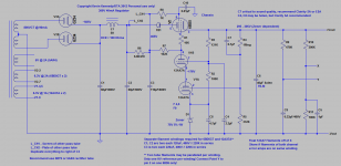
I'm still using 6BD5GTs in my power supply, the previous supply which was shared between the two channels utilized a 6V6 as the pass tube, but was otherwise fairly similar. I'm not able to directly compare the two types in this supply, but I would expect the performance to be comparable with either type.
The new supply is a significant improvement over the old single supply partially because the supply impedance is not common to both channels reducing cross-talk, and I've slightly retooled the cascode error amplifier for better operating conditions in this specific application. The effective plate voltage is also deliberately 100V higher than in the other supply (used a power transformer I had on hand) so the pass tube does not run quite as close to saturation, and the transconductance should be significantly higher - lowering source impedance slightly. The final supply is also at least 12dB quieter than the original in terms of noise and ripple.
The new supply is a significant improvement over the old single supply partially because the supply impedance is not common to both channels reducing cross-talk, and I've slightly retooled the cascode error amplifier for better operating conditions in this specific application. The effective plate voltage is also deliberately 100V higher than in the other supply (used a power transformer I had on hand) so the pass tube does not run quite as close to saturation, and the transconductance should be significantly higher - lowering source impedance slightly. The final supply is also at least 12dB quieter than the original in terms of noise and ripple.
No further problems to report at this time, the design is stable. Finally..
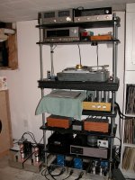
The current set up consists of an Ortofon SPU Meister Silver GM on a Schick arm on a TD124/II. The output of the SPU is fed to a pair of Lundahl LL1941 configured for 1:16 step up which drives the Muscovite.
It is extremely quiet, at anything below an insane volume setting I'm not aware of any noise at all until the needle lands on the lead in groove and then it is pretty obvious just how high the volume is set.
The resolving power of this design is a considerable improvement over my last design. I'm frankly surprised at how much information is contained in those tiny little grooves. I have to admit the cartridge plays a rather major role here too, I have several other lesser cartridges and their shortcomings are rather obvious in direct comparison and over time. There are more differences in performance capability than I had imagined would be the case as I climbed the cartridge price ladder.
I've attached a picture of the finished units and power supply in their permanent homes.. The phono pre-amps have blank wood panels and the SUT is sitting between them.
I have to admit the digital gear and tuner almost never get turned on, I'm listening almost exclusively to vinyl unless the music is background to some project activity on my work bench.
Attachments

Good to hear that you got to the happy place with this project! I have serious plinth and tonearm envy when I see that picture.
Yeah, it's a nice deck. Gotta love the GM70 glow too! Glad to hear it's stable now, Kevin. I'll probably start gathering parts in a few weeks. It'll take me a while to pull it together though.
Hi Carl,
You know where to find me for any questions you might have. I'm very pleased with the end result finally.. The final power supply is a major improvement over the bodged together temporary 6V6 based supply you heard.
The output ripple is about 1/5th that of the temporary supply, and the fact that each channel has its own independent B+ regulator has resulted in significantly better imaging and depth. Bass is even tighter.. I have to admit I was surprised at the differences, an all around improvement.
I did tweak the supply design significantly as is obvious from the supply schematic.
Good to hear that you got to the happy place with this project! I have serious plinth and tonearm envy when I see that picture.
The plinth is quite a story, there will be a replacement soon for what I called the "cracked slate plinth" which did not survive the trip from Vietnam intact. I spent several hours with epoxy gluing three of the four layers back together, quite a few hundred individual pieces of slate. I'm better at figuring out puzzles than I had reckoned, but then I was very motivated..
This plinth will live on as the base for my other TD124.I love the Schick/SPU combination - this arm and cartridge gives me the best sound I have ever had in my own system.. So much so that the digital part of my system is languishing from lack of use..
I'm still puzzled at how I missed that solder joint as I am pretty meticulous, and because the connection was intermittent it was hard to diagnose at first. I was completely focused on the fact that I was using a beam power pentode instead of my usual beam tetrode choices that I rather missed the forest for the trees. There were certainly issues with the choice of this tube, but my usual approach clearly addressed those problems. Some simple diagnostics and a lurking suspicion finally got me to the cause. Sort of embarrassing actually..
- Home
- Source & Line
- Analogue Source
- The "Muscovite" 6S3P Tube Phonostage