Maybe he hit a problem or two that extended his downtime?
Yeah , I slept.

OS
Last edited:
So what's the "good stuff" that you've been talking about? Should I try the Teflon?
- keantoken
Teflon is literally burnproof (good for hot ops boards - beyond FR-4) , VERY high dielectric , slightly flexible. Actually overkill for our amps ... bigtime. Used for High energy , high power RF/microwave amps.. typically.
OS
When you get to my Dad's age one does that !I slept
I just wanted Krisfr to have full BW. He must have DSL ... only 112kbs , my max is over 500!
OS
My down is OVER 1 Meg, what is YOUR up? Not your down speed.
keantoken get some CEM or FR4 that is all you need...
I read this thread everyday and it was one of the most interesting thread I saw.
I do understand that OS did a large amout of work , very fine work, and we must thank him for that.
I did have a chance to learn a lot of stuff.
I would be glad if the schematics and layout could be merge together and have a fair picture of the project.
If somebody go for contruction of a kit I may by one to buid an amp and experiment.
The projects are here.... Current Directory: /WEBSITE/MONGREL/
I have every one in there built and WORKING at my home except the pb120 (repeet built that). No hum , no thumps , no issues. As DX would say... trust.
I will let everybody in on my "kit" .... I am making a standardized AX , the "Bob cordell" amp style. It will have the jumpered/unjumpered supply option (separate V stage option) , CMC,TMC,TPC compensation capable , 120w/8R with cap multipliers ... an full "all in one" offering.
I thought about whether to share as well as sell. I think a DIY'er should have the option to make his own board. just as many or more would go for the short kit or full kit (PCB/all the parts).
In the design phase, my only decision is how much onboard capacitance to include. At a lower rail voltage (45-50VDC), 10KuF/@63v would be easy to implement. This would allow for just a bridge/trafo to have a full working amp.
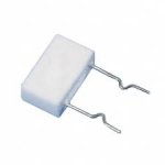
(below 1 is my initial work).The layout of the power and ground routes is the most important , I am using 10mm .22R/5w emitter resistors (below 2). Sprint layout works VERY good on Win7 !!
OS
Attachments
Last edited:
My down is OVER 1 Meg, what is YOUR up? Not your down speed.
keantoken get some CEM or FR4 that is all you need...
With you and others going simultaneously , I was averaging 450-500kbs upload. I thought if I let you use the server exclusively , things would speed up. BTW , my upload is 600KBs (single users have hit 500+ before) , DL is 4Mb/s+.
OS
With you and others going simultaneously , I was averaging 450-500kbs upload. I thought if I let you use the server exclusively , things would speed up. BTW , my upload is 600KBs (single users have hit 500+ before) , DL is 4Mb/s+.
OS
All I ever saw was 115k or so. I have hit over 1M on other sites...
Not a problem, Task complete and Wonderful... Thanks
Sorry for confusion , it is the EX. A VERY simple symasym/goldmund type design. I am still using/testing it. (Below 1) What is so crazy about this design , it sounds better with the "ancient" MJE340/350 . I will add into the "collection" soon ... it works very good.
OS
. I will add into the "collection" soon ... it works very good.OS
Attachments
I've got that "dilapidated" state as well. You've got to name them something. Easier to say "EX" than "updated hitachi topology" or "goldmund clone".
As far as the 340/350 pair , they are worthy of a "righteous" (accurate) model. For now , I just build and listen (no other choice). My observations are that they sound like "heaven" .. are more stable (higher Cob might be better for a VAS).
OS
You've got to name them something. Easier to say "EX" than "updated hitachi topology" or "goldmund clone".As far as the 340/350 pair , they are worthy of a "righteous" (accurate) model. For now , I just build and listen (no other choice). My observations are that they sound like "heaven" .. are more stable (higher Cob might be better for a VAS).
OS
I have listened ... for hours (below - ugly CM's) .... can not note any audible changes with the diode/ CM. I did not let any non-objective statements or opinions sway my decision. Same music , 2 pairs voltage stages (w/diode - no diode BX1.3's) , same power supply/output stage and bias. NO change.
. . .
Edit: where this "diode trick" DOES seem to have major effects, is in a non-beta enhanced VAS where the CM/LTP sees more load (also according to LT).
OS
Question: Is EX and/or Frugalamp a non-beta enhanced that could benefit from magic diode current mirror? Please pardon that I just don't know what the term "beta enhanced" means. I was just all fascinated because this diode trick could increase the performance of a simplified amplifier, but I don't really know what that means either.
I was just all fascinated because this diode trick could increase the performance of a simplified amplifier, but I don't really know what that means either.
The "magic diode" trick is no more effective than the use of a suitably chosen series resistor between the unloaded side of the LTP and the CM.
In the case of the Silicon Chip ULD2 , that works out to approximately 130 ohms.
This assumes of course, that both halves of the LTP are well matched for both HFE and VBe, and are preferably thermally coupled.
With low rail voltage Class A amplifiers such as the SC 15 and SC 20W,
the dual transistors LS313 and LS352 are ideal for this purpose.
I agree with SandyK. It could be diode, diode + trimpot or trimpot alone
on the unloaded side of the LTP to set their collector voltages as close as possible to 0.0mV.
But I have seen the trick to work only when the VAS is preceded by a buffer stage of some sort.
Hi Samuel
We are using a series schottky diode and trimpot to great effect in the Class A HA/ preamp at the attached link.
This is even more effective than an earlier version where an emitter follower was used in between.
We are now able to keep within +-1mV difference between the collectors of the LTP when correctly adjusted,and it DOES sound a little better again with this close adjustment.
This has also been confirmed by several builders using the same schematic, but an earlier version of the PCB.
Regards
Alex
Rock Grotto Audio Forum - For Headphones - Headphone Amps - Amplifiers - X-Can V2 - Musical Fidelity - headphone Discussion - Amplifier Discussion - DIY - Amplifier Kits - Projects - SCHA - Sennheiser - Beyer - Grado - Audio Technica - Headphone amp reply 971
You are right SandyK, but I should have added cascoded VAS as well. I have tried this and it works great. Try removing the cascode and with a single transistor VAS, I doubt it. In some cases, I have seen the circuit become very unstable or a large DC appears at the output.
- Status
- This old topic is closed. If you want to reopen this topic, contact a moderator using the "Report Post" button.
- Home
- Amplifiers
- Solid State
- The MONGREL (supersym II)