So what do you (OS) or others feel about speaker protection with the Mongrel ?
I'm confident in my soldering and assembly abilities, but I have no way of knowing what the risk is of a catastrophic, speaker-killing failure is. Is there anything about this design that makes it less likely ? Do failures occur mainly due to "predictable" things like under-rated parts, over-use (hours, temperature), power line garbage, turn-on stresses, or do transistors just sort of up and die ?
In my case, I wouldn't mind too much if some of my silicon smoked, but I'd be very unhappy if I had to shell out for a new set of drivers. I kind of want to avoid speaker relays, but I'm toying with the idea of adding a triac to shunt output to ground if case of excessive DC.
Are there any plans in the works to make speaker protection part of the design ?
Never had any issues with failure. Everthing here is almost "double de-rated". All semi's are 80% + over voltage (even at 75+V), caps are at least 50% and all the currents are low (2-6.5ma) . If you properly heatsink the OPS , throw out the A/C , these are good to 40c outdoor (jungle) use. I will make the "omni" when I get a few $150 dayton woofers. The protect circuit is best left as a add-on.
OS
Okay, cool
I had looked in the Omni protect directory and saw it was empty. Hadn't noticed the zip file. Now I'll have another schematic to study.
I'm building the Mongrel amp and a pair of Zaph Audio designed SR71 speakers (speakers first). The Seas drivers are pretty spendy for me, so I'm hoping its a one-time sort of thing.
GND noise
1. Could we discuss the measurement technique for GND noise.
It seems that there is no reference point against which measurement
of GND noise can be made. The material I find refers to differential measurement between 2 points of a GND conductor/ trace. This does not provide a reference for single ended measurement.
So what is the noise of G1 and G2 on the PB120N POWER BOARD ?
2. AX1.3VB:
Q11 the VAS CCS sense transistor matches Q12 a power device. Is the tracking of the 2 devices of great benefit ?
Direct ground rod or "technical ground" (the earth itself). Any ground noise will be switching pulses injected by your new high tech stuff in addition to both the 60hz and music produced pulses contributed by the bypass components.
G2 will always be less since no real current pulses are being bypassed by the circuitry associated with it.
Q11 , they hold the heatsink up nicely..
 Both are high gain , no problem there either , they are also at the same temp. coefficient as the rest of the VAS (same Heatsink). In addition, the CCS has to endure full rail to rail voltage (160V) , why not use a 300V /Vce device ?
OS
Wheys, it lives and makes sound!
What quiescent current should the output devices have? (im using MJL4281/MJL4302) and what method do you use to measure them?
Measure 11-15mv across the .22R 5w resistors. This will give 50-75ma current on op devices.
OS
Again, thank you, me personally not interested in power.
Amplifier is a reliable, worked with the test transformer(2x45V 500W) almost all day in full force.
Of course the artificial resistance, several resistors in series.
Since I have Fullrange speakers (sonido) a few watts is a lot for a listening.
Greeting
Hi Nikko!
Series resistors?
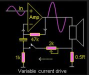
Here's a handy adapter for full range speakers:
Attachments
Wheys, it lives and makes sound!
What quiescent current should the output devices have? (im using MJL4281/MJL4302) and what method do you use to measure them?
Try 11mV to 26mV voltage drop on emitter resistors and LISTEN! Differences could be very audible so y you must listen to find the sweet spot.
P.S. For this tests it`s necessary that amp has accurate thermal bias tracking...
Hello Daniel, long time no see.
It seems at first dubious to me to make the amplifier perform the function of the resistor, when a few passive components will produce exactly the same effect easily. That is unless of course, the series resistors were large enough to make the speaker not very sensitive, so that a higher power amplifier were needed. In this case, it is more economical to use current drive, all other things equal. At this point it occurs to me however, that perhaps adapting the amplifier to perform also the function of the resistor would actually eliminate a component from the signal path, if we accept that the amplifier's distortion will be present whether using current or voltage drive (although the distortion mechanisms may change).
Hmm.
- keantoken
Some would say it is delusional to be able to discern a "sweet spot" in class AB bias. With the AX , it is harder ... since TMC reduces the X-over distortion over a wider range than conventional compensation. I still can hear the difference , so maybe I'm crazy ... oh well...Try 11mV to 26mV voltage drop on emitter resistors and LISTEN! Differences could be very audible so y you must listen to find the sweet spot.
P.S. For this tests it`s necessary that amp has accurate thermal bias tracking...
I've both listened to 10-25mv settings and observed the stability of these settings between 10 - 50C ambient ... the AX is VERY stable thermally and sound wise - not much difference (rock solid). Next , the first "all in one" 120 watt AX board is in the works. I removed even the slightest thump , hum , noise .. all the "bugs" have been thoroughly "exterminated".
I will perfect the "EX" next , it will be my "goldmund" , complete with "low tech" mje340/350's , lead comp and slightly overcompensated phase margin. It will be the voltage stage to do sub duty , bi-amping , or HT.
OS
Crap!
Just powered up PB120N with BX1.3VB and the smoke fell out of R8. Just realised that the voltage board is now designed to go upright which reverses the connectors to the power board. Not sure what damage this has done yet but I'm getting 60v on the output, with the bias trimmer set at 200r.
Pete
Just powered up PB120N with BX1.3VB and the smoke fell out of R8. Just realised that the voltage board is now designed to go upright which reverses the connectors to the power board. Not sure what damage this has done yet but I'm getting 60v on the output, with the bias trimmer set at 200r.
Pete
Check everything , you reverse biased every junction on the voltage board ... OOOPS.
OS
Yes I know. I'll start again tomorrow. Its nearly midnight here.
I'd say all the trannies will be toast.
Do you think this would also do any damage on the voltage board?
Yes I know. I'll start again tomorrow. Its nearly midnight here.
I'd say all the trannies will be toast.
Do you think this would also do any damage on the voltage board?
Check EVERYTHING (both boards DMM B-E / C-E).
OS
turn the bias adjustment back to zero bias current.Check EVERYTHING (both boards DMM B-E / C-E).
OS
Start up using the bulb tester. It will probably light telling you it's scrap.
But you can start measuring voltages and maybe identify which components are still working. However "still working" is not equal to reliable future operation.
Hi OS.
I need a bit of help to finish up "Little Bro" especially the really confusing shopping.
I have:
MJE15032G, MJE15033G
bd139, bd140
bc547, bc548, bc549
2sc9012, 2sc9013
KSP2222ABC
and
MR756, 1n1418, 1n4004, 1n5405, led, 6v, 9v, 12v
and
NJW1302G, NJW3281G
What semiconductors do I need to buy to finish up?
Thanks!
- Status
- This old topic is closed. If you want to reopen this topic, contact a moderator using the "Report Post" button.
- Home
- Amplifiers
- Solid State
- The MONGREL (supersym II)