Hi Magz, first of all I agree with Tubelab...after a few years of wear and tear the dielectric strength of the plastic case may change....to me its a bit like a car...once its working okay DON'T lift the Hood and start tinkering around...the same I guess would go for your Amp...once its up and running you dont want to be lifting this 100 pound monster on its end to carryout repairs...so all precautions now just maybe worthwhile. On the equalizing resistors I would personally put them in as it will do no harm....Try RF Parts they may have what you are looking for in the High Ohm range
https://www.rfparts.com/
Read up a few posts...I ordered kapton tape and resistors already.
This is only for the bypass caps (decoupling). These are connected to . . . .
Ah, I see. Thanks.
While we're here, for anybody looking , here's another HV resistor.
I just got this out of my Tubelab Email accounts spam folder. I think it was sent yesterday.
Electronic Goldmine
Kapton tape for less than $5 per roll. Note I have ordered parts from these people several time with no bad reports. Most of my purchases have been RF parts. It is common for some of their stuff to sell out quickly, while other items hang around for years as the price drops toward zero. All is surplus stuff.
Just finishing up monoblock #1. It should be ready to go this week. Shaping the teflon sockets by hand, to fit inside the pyrex cylinder around the 833, was pretty time consuming, but it's a nice tight fit now with brass inserts in place to screw into to hold the cylinder.
Today I brought the 833 B+ supply up on the Variac over the course of an hour, all the way to 2350V. No problems detected. So now all the individual subcircuits have been tested with just a few more connections to be made.
Stay tuned.
Today I brought the 833 B+ supply up on the Variac over the course of an hour, all the way to 2350V. No problems detected. So now all the individual subcircuits have been tested with just a few more connections to be made.
Stay tuned.
OK, it's Christmas Eve and I'm 99.99% done.
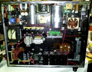
Picture 1 is the final (hopefully!) inside construction.
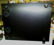
Picture 2 is the bottom view after I closed it up. The two square items are 3" diameter inlets with low-restriction air filters.
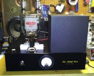
Picture 3 is the amp upright, with 833 mounted. All that's left is to attach the plate and grid wires, slip the Pyrex cylinder on and fire it up!
Here's where the torture comes in...I'll have no more time today (Christmas Eve with my mother-in-law) or tomorrow (Christmas Day at my Sister's house), so the earliest I can fire it up will be Thursday.
Talk to ya then!
Picture 1 is the final (hopefully!) inside construction.
Picture 2 is the bottom view after I closed it up. The two square items are 3" diameter inlets with low-restriction air filters.
Picture 3 is the amp upright, with 833 mounted. All that's left is to attach the plate and grid wires, slip the Pyrex cylinder on and fire it up!
Here's where the torture comes in...I'll have no more time today (Christmas Eve with my mother-in-law) or tomorrow (Christmas Day at my Sister's house), so the earliest I can fire it up will be Thursday.
Talk to ya then!
Attachments
Congratulations on a very nice build.
I've been following this thread closely.
About waiting a bit till you can fire it up: it isn't easy, but often I do it to myself on purpose: don't take the risk on overseeing things in the heat of the moment and frying something precious. Next day (or two), with a clear head going over everything one more time and go...
Happy Xmas!
I just got this out of my Tubelab Email accounts spam folder. I think it was sent yesterday.
Electronic Goldmine
Kapton tape for less than $5 per roll. Note I have ordered parts from these people several time with no bad reports. Most of my purchases have been RF parts. It is common for some of their stuff to sell out quickly, while other items hang around for years as the price drops toward zero. All is surplus stuff.
I have no idea whether it's relevant in this case or not but I do remember having a few feet of kapton insulated wire seven or eight years ago that was from stock that I was told NASA had liquidated. Some time later I heard that NASA had stopped using it because it was a fire hazard. Doing a brief search just now I saw a couple of hits that mention kapton wire being implicated as the cause of airplane fires . Apparently it burns really well. Does it matter here?
I have no idea whether it's relevant in this case or not but I do remember having a few feet of kapton insulated wire seven or eight years ago that was from stock that I was told NASA had liquidated. Some time later I heard that NASA had stopped using it because it was a fire hazard. Doing a brief search just now I saw a couple of hits that mention kapton wire being implicated as the cause of airplane fires . Apparently it burns really well. Does it matter here?
Polyimide (kapton) is used as the outer coating on gas chromatography capillary columns, and we routinely run them at 300C or higher with no issues in my lab. If my amp ever gets to 300C I'll have bigger issues than the kapton tape igniting.
There are different grades of polyimide, but I can't imagine any that would have issues at the temps in an amp, especially since it's only being used to insulate the chassis from any unlikely short circuits.
Thanks for the heads-up, though!
On reading up further on the kapton issue, I'd probably avoid using kapton-insulated wires in a HV amp due to the issue of "arc-tracking" along wires, which can spread a short-circuit from a worn wire initiation point into other wires. As a high-dielectric insulation applied to the chassis panel, however, I'm not sure the same issues apply.
I know little about Kapton tape, however the issues I read about with aircraft had more to do with durability. It's not great for wiring in mechanical environments such as vehicles and machines with moving parts or excessive vibrations.
If you are using it as a stationary insulator, (as you are) you should be OK. It's far bettter then nothing.
If you are using it as a stationary insulator, (as you are) you should be OK. It's far bettter then nothing.
I know little about Kapton tape, however the issues I read about with aircraft had more to do with durability. It's not great for wiring in mechanical environments such as vehicles and machines with moving parts or excessive vibrations.
If you are using it as a stationary insulator, (as you are) you should be OK. It's far bettter then nothing.
Yes, I believe the failure mode is wear from abrasion during use, causing a short circuit between wires, the heat of which ignites the kapton. The burn travels down the wire into wire bundles, and then it all goes up. A very different situation, I agree.
Fired it up today, and...nothing.
Kept blowing the fuse on the filament/driver circuits. So, I opened it up and started the process of elimination. First I looked for obvious shorts or burnt parts and found nothing. When I only connected the filament supply to the soft start board, that worked fine. Then I disconnected the filament supply and connected the driver supply, and the fuse blew, so I knew the issue was in the driver supply. I disconnected the driver PT from the rectifier, and that worked fine, no blown fuses. When I diconnevted L1 and checked it at that point, the fuse blew, so it looked like a rectifier issue. I took out the rectifier board and found a shorted diode in the bridge.
Fortunately I have another rectifier board I made for the other mono, so I'll pop that in and hopefully that will be the fix. Hopefully something else isn't causing the diode to blow...I did check the rest of the PS circuit for shorts and didn't find any, so I'm thinking bad diode.
")
The diodes are rated for a repetitive surge current of 13A and a max forward DC current of 5.9A. The fuses that kept blowing were 3.15A, a current the diodes should have been able to handle, so I'm pretty sure this was a faulty diode instead of a short somewhere else that blew the diode.
I tested the entire driver circuit twice before this with no issues, but it could have been a latent defect that just picked this moment to short. In any case, I'll find out tomorrow when I swap in the other bridge.
I tested the entire driver circuit twice before this with no issues, but it could have been a latent defect that just picked this moment to short. In any case, I'll find out tomorrow when I swap in the other bridge.
The diodes are rated for a repetitive surge current of 13A and a max forward DC current of 5.9A. The fuses that kept blowing were 3.15A, a current the diodes should have been able to handle, so I'm pretty sure this was a faulty diode instead of a short somewhere else that blew the diode.
I tested the entire driver circuit twice before this with no issues, but it could have been a latent defect that just picked this moment to short. In any case, I'll find out tomorrow when I swap in the other bridge.
Magz, is your bias voltage present when the driver circuit is energized? I assume your "driver" circuit is your B+?
Magz, is your bias voltage present when the driver circuit is energized? I assume your "driver" circuit is your B+?
This is the 6E5P circuit B+; the 6E5P is the driver tube for the 833. Bias is provided by diodes in the 6E5P cathode, so it is definitely present, and in any case, the fuse blows before the 6E5P even has a chance to conduct, and before the 833 filament even starts to glow (blows within one second of the soft start).
The 833 is energized via a separate switch, which has not been turned on at all due to the issue with the 6E5P circuit. The intended startup sequence is:
1) Power switch thrown, 6E5P B+ and heater and 833 filament (Rod Coleman regulator) and 833 bias supply all soft started.
2) After warmup period, second switch is thrown, and 833 B+ is soft started.
The entire 6E5P circuit was tested twice before this (I posted square wave shots), and the only thing different is that the bias shunt regulator was connected to the 833 filament this time to float it 30V above the grid, which is direct coupled from the driver circuit. That connection shouldn't draw any current since the only connection to ground is the ground of the shunt regulator. I checked the filament and it isn't shorted to any other part of the tube, so I'm pretty convinced the issue was just a bad rectifier diode.
The next couple days are fairly busy for me, but I should be able to replace the bridge board tonight and check it out again.
Last edited:
So the issue was the shorted rectifier diode. I replaced the bridge rectifier board for the 6E5P and all was well again. So, I put everything back together and fired it up, and...
SUCCESS!
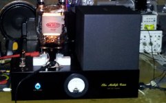
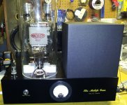
The amp works. Picture 1 is the amp with the 833 at 140mA, glowing away hot, hot, hot...
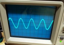
Picture 2 is a 2kHz sine wave at .05V input.
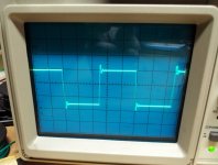
Picture 3 is a 2kHz square wave, nice and square but with a little bit of overshoot and wiggle on the front.
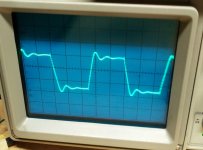
Picture 4 is a 10kHz square wave.
Picture 5 is the amp with the pyrex glass cylinder installed; I need to make something to cover the top of the cylinder, eventually.
So overall I'm happy. I didn't get to do any listening today as it's late and everyone is in bed, but that will come soon enough.
PS: all testing was done with a 4 ohm, 100W dummy load on the output.
.
SUCCESS!
The amp works. Picture 1 is the amp with the 833 at 140mA, glowing away hot, hot, hot...
Picture 2 is a 2kHz sine wave at .05V input.
Picture 3 is a 2kHz square wave, nice and square but with a little bit of overshoot and wiggle on the front.
Picture 4 is a 10kHz square wave.
Picture 5 is the amp with the pyrex glass cylinder installed; I need to make something to cover the top of the cylinder, eventually.
So overall I'm happy. I didn't get to do any listening today as it's late and everyone is in bed, but that will come soon enough.
PS: all testing was done with a 4 ohm, 100W dummy load on the output.
.
Attachments
Last edited:
- Home
- Amplifiers
- Tubes / Valves
- The Midlife Crisis - My 833C Amp Build