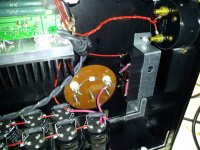
I decided to add some film decoupling caps to the output stage power supply, to help out the 7 series TSHA electrolytics, so I put three 10uF, 1000V Mundorf MTubecaps in series to make a 3000V, 3.33uF decoupling cap, with an ESR of 39mohm. The 7 series TSHA caps have an ESR of 1.2 ohms, or 31X higher than the decoupler. I fabricated a bracket for them and bolted them to the chassis using the output transformer bolts - it worked out neatly in terms of the mounting (see picture). The caps connect directly to the OPT B+ connection with a very short 18ga lead, with the other end connected to the circuit ground.
I feel better now about what's in the direct signal path for the output stage. I'm sure it will make a big difference in the sound, even if it's only mentally ;-).
I feel better now about what's in the direct signal path for the output stage. I'm sure it will make a big difference in the sound, even if it's only mentally ;-).
Attachments
833
I agree with you it looks a bit to close the chassis...not only that but I would have mounted them on a piece of Paxolin (or suchlike) and had them vertical with the connections upwards. In addition to having some equalizing resistors across them as well as an HT Bleeder Resistor to ground
I agree with you it looks a bit to close the chassis...not only that but I would have mounted them on a piece of Paxolin (or suchlike) and had them vertical with the connections upwards. In addition to having some equalizing resistors across them as well as an HT Bleeder Resistor to ground
Yes, I thought of the proximity issue too, while trying to get the cap as close to the connection as possible (as decouplers should be). The pin for the cap is bent away from the chassis and coated with a couple layers of corona dope (3000V/mil dielectric strength). I was also planning on sliding a piece of insulation under the pins (there is some space for it), but just haven't done that yet. The caps aren't glued down, just bracketed, so it's not a big deal to slide some insulation under them.
I was under the impression that with film caps the equalizing resistors usually aren't needed because the film caps are much more consistent than electrolytics. However, in the name of extra safety margin I may add them in anyway just in case.
Thanks for the observations - it's always good to have another set of eyes check things out.
.
Last edited:
Regarding the balancing resistors, PP film caps have leakage in the low nA range. Balancing resistors calculated according to the usual method for electrolytic caps would thus need to be in the range of 10000Mohms to allow ~10x the leakage current to flow.
Anyone know a good source for Gohm resistors??
Seriously, though, I can't find any references recommending balancing resistors for film caps. If the capacitances are close to each other, and the leakages are so extremely low, it doesn't seem that resistors would be needed - am I missing something?
Anyone know a good source for Gohm resistors??
Seriously, though, I can't find any references recommending balancing resistors for film caps. If the capacitances are close to each other, and the leakages are so extremely low, it doesn't seem that resistors would be needed - am I missing something?
However, in the name of extra safety margin I may add them in anyway just in case.
The dielectric in a film cap is much better that the oxide layer in an electrolytic, so the equalizing resistors can be a much higher value but finding small resistors with a suitable voltage rating can be difficult.
Absolutely, some insulation and/or a different position would be good.
I would also question the dielectric strength of the plastic case the caps are made of, maybe not now, but after 10 years of heat, humidity, and dust. Reccomendation: Kapton tape is your friend. I bought a 2 inch wide roll at a hamfest several years ago for $30. Its way neater than corona dope and looks better. I would put a layer or two on the chassis under the caps and the connections, and some on the mounting bracket.
I feel better now about what's in the direct signal path for the output stage. I'm sure it will make a big difference in the sound, even if it's only mentally ;-).
The power supply in my 845 SE amp is a voltage doubler made with 5AR4's on a 480 volt industrial control transformer. It has two banks of cheap Panasonic electrolytics in CLC (choke in ground leg) and makes 1100 volts. I added an old 4 uF 4KV oil cap directly to the OPT B+ connections and there was a noticable improvement.
The dielectric in a film cap is much better that the oxide layer in an electrolytic, so the equalizing resistors can be a much higher value but finding small resistors with a suitable voltage rating can be difficult.
I would also question the dielectric strength of the plastic case the caps are made of, maybe not now, but after 10 years of heat, humidity, and dust. Reccomendation: Kapton tape is your friend. I bought a 2 inch wide roll at a hamfest several years ago for $30. Its way neater than corona dope and looks better. I would put a layer or two on the chassis under the caps and the connections, and some on the mounting bracket.
Thanks for the kapton tape recommendation, I'll have to pick some up!
So, from your comments I assume you feel the balancing resistors are necessary, correct?
I ordered these 1000V, 100M resistors for the decouplers, just to be safe:
Ohmite MOX300 Series
Should give about 8uA of current, plenty to swamp out the nA level leakage of the film caps.
.
Ohmite MOX300 Series
Should give about 8uA of current, plenty to swamp out the nA level leakage of the film caps.
.
Last edited:
+1 for Kapton tape. It's expensive but it is very hard to beat performance-wise. It works wonders at hot temperatures as well.
~Tom
Already ordered a 4" wide roll from Amazon. Not a bad price, either. I'll stick that in there when I get it.
")
4" wide. Damn... How much did you get for that kidney anyway?
~Tom
$35.00...
I was just bumbling by so sorry if I've missed the relevent info but on the topic of balancing resistors why not just double purpose them as your bleeder resistors and use a lower value?
This is only for the bypass caps (decoupling). These are connected to the main electrolytic cap bank which has 5W 47k bleeders, so it should drain through those. Keeping these at a high value keeps the dissipation low, so I can use small resistors and not generate unnecessary heat (there's plenty already!).
.
Last edited:
$35! Damn! Good deal!
~Tom
They have more...
Amazon.com: 1 Mil Kapton Tape (Polyimide) - 4" x 36 yds: Office Products
It's rated at 8000V according to the description.
833
Hi Magz, first of all I agree with Tubelab...after a few years of wear and tear the dielectric strength of the plastic case may change....to me its a bit like a car...once its working okay DON'T lift the Hood and start tinkering around...the same I guess would go for your Amp...once its up and running you dont want to be lifting this 100 pound monster on its end to carryout repairs...so all precautions now just maybe worthwhile. On the equalizing resistors I would personally put them in as it will do no harm....Try RF Parts they may have what you are looking for in the High Ohm range
https://www.rfparts.com/
- Home
- Amplifiers
- Tubes / Valves
- The Midlife Crisis - My 833C Amp Build