milion people, milion tastes.Why should I pay 2000€ more per channel when I can't hear a difference?
i think this decision is better than corvette
")
OK, I'd like some help thinking through the power dissipation and heat sinking requirements of the AOT1N60 mosfet driver. Here's the way I figure it.
Looking at the graph in post #23 of this thread, at full power the circuit is pulling grid current about 1/3 of the time. Assuming the worst case scenario of a square wave of grid current at 180mA plus the 32mA DC plate current for the 6E5P, the average current would be:
.67*32mA + .33*212mA = 91.4mA
Average power dissipation at full power would be:
91.4mA*(400V-216V) = 16.82W
The AOT1N60 is rated for 41.7W at 25C and derated at 0.3W/C to 31.2W at 60C. I'm hoping to heat sink the mosfet sufficiently to keep it at 60C, so the 31.2W figure would be applicable.
So, for a sanity check, does this look about right? Sounds like the AOT1N60 should survive, correct?
If not, I could upsize to the AOT2N60, which is rated at 53W at 60C, but which has twice the capacitance of its smaller brother.
Thoughts?
Looking at this another way, using the Safe Operating Area graph on the datasheet, the AOT1N60 chip looks like it's good up to ~800mA max for 300uS pulses at 200Vds (25C case temp), so it appears it should survive 180mA pulses just fine given proper heat sinking. Since I don't intend to be running at a full 200 watts of power for very long periods of time, I'd think this ought to be sufficient.
.
Last edited:
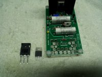
One of the key design features of this amp is the use of a shunt regulator under the cathode of the 833 to hold it at ~247V and allow adjustability of the bias, while sinking the cathode current from the 833. I'm using shunt regulators from K&K Audio, based on the Salas SSHV design with a cascaded CCS in front. At first glance, the shunt transistor, IRF840 seemed like it had plenty of power dissipation capability (125W), but looking closer at the heat sinking required, junction to case thermal parameters, package size, etc it will be really close to blowing up as it tries to sink its 15mA set current plus all the current passing through the 833. In the interest of reliability, I've decided to upsize the Mosfet from the IRF840 to the IRFP450A, which has 190W power dissipation and comes in a TO-247 package for much improved heat dissipation.
The junction to case thermal resistance for the IRF840 is 1degC/W, which drops to 0.65degC/W in the IRFP450A. That's a big difference when you're trying to dump that much heat through the case into the sink/chassis. The Mosfet will be mounted off the board on a solid 10mm thick block of aluminum bolted to the chassis.
A snapshot is attached showing the two Mosfets and the regulator board.
Attachments
Last edited:
Hi Magz,
Are you sure that you build a tube(valve) amplifier? There is a lot of transistors in your Project...
I am really curious on the result.
If I'm right, you want to use 2300V - 247V = 2053V for the anode voltage.
Makes 2053V x 161mA = 330,5W...plus 10V x 10A = 100W, this are 430W for all...with no audio Signal...continuously...
I'm using 950V anode voltage with 185mA, this are 175W + filament 100W = 275W per tube(valve)...and they are getting hot, really hot (all the carbone of the anode is glowing after one hour...). I'm using a smal (80mm) 5V PC Fan for cooling (because the noise) from the bottom.
In my first tests the wires where desoldered from the anode caps...while no cooling...275W only...
May be you can cool down your 833 at 430W but it should be sound like a hovercraft....
Good luck, Matthias.
It will be a heat generator, for sure. I'll be using a finned aluminum top cap for the anode, and an 80mm 12V brushless fan underneath blowing up (33CFM); the 833C will be inside a 6 inch ID pyrex glass cylinder which I hope will help to direct the airflow around the 833C envelope more efficiently. If it still gets too hot I can always back down on the current a bit...we'll see.
About the transistors...I use what I think is best for the job, tubes for voltage amplification and SS for regulating and driving current. I think the combination leverages the strengths of both.
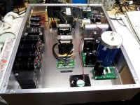
The other reason I selectively use SS is SPACE! Attached is a picture of the components (most of them) laid out in the Landfall Chassis, which is 23" x 18" x 4.25", and the fit is pretty tight! The transformers for the driver and power tube supplies, the first choke for the 833C and the OPT will be on top of the box. From left are the 833 B+, 833 Filament and Driver B+, heater, bias supplies. I haven't built the input board yet with the gyrator; the empty board is tucked in the front right corner of the chassis.
About the transistors...I use what I think is best for the job, tubes for voltage amplification and SS for regulating and driving current. I think the combination leverages the strengths of both.
The other reason I selectively use SS is SPACE! Attached is a picture of the components (most of them) laid out in the Landfall Chassis, which is 23" x 18" x 4.25", and the fit is pretty tight! The transformers for the driver and power tube supplies, the first choke for the 833C and the OPT will be on top of the box. From left are the 833 B+, 833 Filament and Driver B+, heater, bias supplies. I haven't built the input board yet with the gyrator; the empty board is tucked in the front right corner of the chassis.
Attachments
Magz: Every 1 kW broadcast transmitter I have worked on using the 833A has a fan above the tube that directs the air blast to the glass between the anode and grid connections. No glass "chimney" is used. This keeps the glass to metal seal within published ratings. Class A single ended is pure dissipation, unlike the Class B audio (modulator) and Class C RF, used in a transmitter.
Some of the other transmitters using the 4-400 tetrode pressurize the chassis, and the air is forced up around the tube, which is enclosed in a glass chimney.
The finned heat radiating connector for the anode and grid is a good idea.
Good luck with the project and long live the 833A's....
Some of the other transmitters using the 4-400 tetrode pressurize the chassis, and the air is forced up around the tube, which is enclosed in a glass chimney.
The finned heat radiating connector for the anode and grid is a good idea.
Good luck with the project and long live the 833A's....
I just love it !!!!!!!!!!!!!
Guys, I just love what you are doing and I am watching with great interest. Quite a few years ago I started to build a PP amp using 833A's....long story short I gave up in the end as everything seemed to be multiplied by a factor of 10 (if you get my drift) it became so large in the end I was having to use a 6 foot rack, it looked more like a Broadcast Transmitter than an Audio Amp. Anyway I gave up but you guys have definitely spurred me on to take another look at it later on this year. So keep all the news and exchange of ideas coming and "may the power/force be with you" !!!!
Guys, I just love what you are doing and I am watching with great interest. Quite a few years ago I started to build a PP amp using 833A's....long story short I gave up in the end as everything seemed to be multiplied by a factor of 10 (if you get my drift) it became so large in the end I was having to use a 6 foot rack, it looked more like a Broadcast Transmitter than an Audio Amp. Anyway I gave up but you guys have definitely spurred me on to take another look at it later on this year. So keep all the news and exchange of ideas coming and "may the power/force be with you" !!!!
It will be a heat generator, for sure. I'll be using a finned aluminum top cap for the anode, and an 80mm 12V brushless fan underneath blowing up (33CFM); the 833C will be inside a 6 inch ID pyrex glass cylinder which I hope will help to direct the airflow around the 833C envelope more efficiently. If it still gets too hot I can always back down on the current a bit...we'll see.
About the transistors...I use what I think is best for the job, tubes for voltage amplification and SS for regulating and driving current. I think the combination leverages the strengths of both.
The other reason I selectively use SS is SPACE! Attached is a picture of the components (most of them) laid out in the Landfall Chassis, which is 23" x 18" x 4.25", and the fit is pretty tight! The transformers for the driver and power tube supplies, the first choke for the 833C and the OPT will be on top of the box. From left are the 833 B+, 833 Filament and Driver B+, heater, bias supplies. I haven't built the input board yet with the gyrator; the empty board is tucked in the front right corner of the chassis.
300 watts only needs convection cooling Hpeter. At least by the spec sheet. You only need forced air when you go to 400 watts dissipation.
Hey Magz. If you got to the bottom of the page on this link there's really good top caps. Much larger then the standard ones. Id use one on bot plate and grid.
Tube sockets, chimneys, and heat dissipating plate caps
Nick
Hey Magz. If you got to the bottom of the page on this link there's really good top caps. Much larger then the standard ones. Id use one on bot plate and grid.
Tube sockets, chimneys, and heat dissipating plate caps
Nick
300 watts only needs convection cooling Hpeter. At least by the spec sheet. You only need forced air when you go to 400 watts dissipation.
Hey Magz. If you got to the bottom of the page on this link there's really good top caps. Much larger then the standard ones. Id use one on bot plate and grid.
Tube sockets, chimneys, and heat dissipating plate caps
Nick
Yup, that's where I got mine from!
Unfortunately I can't use the supposedly even better caps that replace the standard cap and connect directly to the inner mounting post, because the standard caps on the Matchlett tubes I have don't have a screw to remove them; they seem to be permanently installed. Still, the eight fins per cap should help a lot in dissipating some of that heat.
small led heatsinks could be used too. after drilling right size hole in center
An externally hosted image should be here but it was not working when we last tested it.
An externally hosted image should be here but it was not working when we last tested it.
An externally hosted image should be here but it was not working when we last tested it.
Hey Magz. I looked at the picture you posted of the tube and I don't understand the problem. Are the top caps too small for the heavy duty cap connectors? The tope caps on an 833 are part of the seal. This is unique to this tube as far as I know. Usually the seal is on the rod that comes through the top and the cap is secured on by a set screw.
You know max gain make a big heat sink top cap connector that has the 3/8" hole in it. Its like the standard heat dissipating cap. But with a larger heat sink. I think I understand what you meant now. I wasn't taking about the type that replaces the top cap altogether. Just the bigger one. Since there is no mechanical connection from the tubes top cap to the conductor, there isn't as much of a problem.
Its plate cap #1 on the list.
Nick
Hey Magz. I looked at the picture you posted of the tube and I don't understand the problem. Are the top caps too small for the heavy duty cap connectors? The tope caps on an 833 are part of the seal. This is unique to this tube as far as I know. Usually the seal is on the rod that comes through the top and the cap is secured on by a set screw.
You know max gain make a big heat sink top cap connector that has the 3/8" hole in it. Its like the standard heat dissipating cap. But with a larger heat sink. I think I understand what you meant now. I wasn't taking about the type that replaces the top cap altogether. Just the bigger one. Since there is no mechanical connection from the tubes top cap to the conductor, there isn't as much of a problem.
Its plate cap #1 on the list.
Nick
Yes, I have the ones with the larger hole, that fit right over the existing top cap. I was just commenting on the other kind they sell that replace the stock top cap altogether, but in talking with MaxGain on the phone, they told me that those were specifically designed for the 4-1000 tube. So I have the correct ones for the 833.
Back to the 833C amp.
I've been mulling over what protection scheme to use for the HV circuit in the amp.
What I've settled on is an 8A slow blow fuse for the mains, arrived at as follows:
3.33A draw for the Hammond 733A at idle (160mA x 2500/120)
1.155A draw for the Hammond 369KX at max power with full grid current
1.5A draw for the 833 filament circuit
Total = 5.985A. Multiply X 1.25 = 7.48A, round up to 8A slo-blo fuse.
Since the Hammond 733A power transformer is rated at 450mA ICAS, the 8A fuse should be plenty of protection as it will blow at ~257mA of B+ current, which is still well within the rating of the transformer. Even if the other circuits are off, the 8A fuse will blow at 384mA from the 733A. This should protect the PT from rectifier shorts or capacitor shorts or the unlikely choke short without needing a separate fuse on the 733A PT.
The 8A fuse, however does not protect the OPT from a short in the 833C tube, which could discharge the main reservoir caps and their 335 joules of energy through the OPT. For that I'll add a 5kV, 800mA microwave oven fuse in line between the last cap and the OPT.
That takes care of over-current situations, I think. Comments?
.
There are also purpose-made high voltage fuses available. A 2500V or better one should be OK.
Some hams add extra protection from 'flashovers' by making a 3-4" length of #30 wire mounted between two ceramic stand-offs. It protects the tube as well as other power components from the power supply capacitor dump in case of an internal arc. It would protect your OPT as well.
#30 is for 500-600mA service at 3-5KV, you may have to experiment. The wire explodes/vaporizes 'instantly' in case of an arc. Much faster than a fuse. You can test this without concern if careful and should find the filter caps still partly full after.
Others put a 10 Ohm 10 watt resistor instead because it limits the peak arc current. It will also explode if you have 20-50uF there.. so it should be shielded. - but 250A pulse might hurt the OPT.
Are you using a spark gap across the primary? It's done in the modulators of AM transmitters and has saved many a huge modulation transformer when something goes wrong. Hams also do this, in sets running 2-5KV which is a typical range for the application. Case in point I run 2500-3000V in my home made AM transmitter and accidentally overdrove the modulator and the gap fired on each half cycle. They help.
Thanks for the suggestions, I'm still working out the whole protection scheme, to get reasonable protection without adding a bunch more components to the circuit. The spark gap sounds interesting as an overvoltage protection device - do you use a spark gap tube or something else?
Last edited:
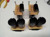
Finished up the 44mF cap assemblies for the 833 LCLC filament supplies, and added 4.7uF Solen PP films as bypasses. I usually bypass large electrolytics with films, but I prefer to use a few uF rather than the .1uF or so often seen. It's made an easily audible difference in some of my projects, and not much of a difference in others, guess it depends on the rest of the circuit as always.
Attachments
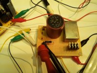
I built one of the Input/Driver boards, containing the grid choke, 6E5P bias diodes (Cree 600V Schottky diodes), gyrator circuit, zener protection diodes and the gate supply resistors for the AOT1N60. Picture 1.
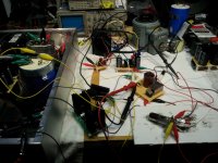
I now had all of the driver circuit components built so I decided to wire it all up (the input/driver circuit and its power supplies) with clip leads and test it. Picture 2.
I fired it up on the variac...no smoke, always a good sign! After a bit of adjustment on the shunt regulator that supplies the MOSFET gate voltage, everything was about where it should be on the DC front, with 216V at the 1N60 source, and 28.5mA coming through at the cathode of the 6E5P.
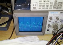
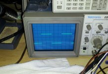
So I then sent some test signals through, 2kHz sine and square waves, and they looked good too! Pictures 3 and 4.
So I can say at this point that this circuit works fine up right up to the 833C tube. Good news.
Time to build the other input/driver board in the first one's (mirror) image!
I now had all of the driver circuit components built so I decided to wire it all up (the input/driver circuit and its power supplies) with clip leads and test it. Picture 2.
I fired it up on the variac...no smoke, always a good sign! After a bit of adjustment on the shunt regulator that supplies the MOSFET gate voltage, everything was about where it should be on the DC front, with 216V at the 1N60 source, and 28.5mA coming through at the cathode of the 6E5P.
So I then sent some test signals through, 2kHz sine and square waves, and they looked good too! Pictures 3 and 4.
So I can say at this point that this circuit works fine up right up to the 833C tube. Good news.
Time to build the other input/driver board in the first one's (mirror) image!
Attachments
Since I had the circuit set up, I decided to test the performance of the AOT1N60 vs the AOT2N60, to see if there were any differences to be seen.
Spec Differences:
The 2N60 is rated for 74W dissipation, as opposed to the 41.7W of the 1N60.
The 2N60 has higher capacitances, with the Ciss (270pF vs 130 pF typical), Crss (2.8pF vs 1.8pF), Cdss (29pF vs 14.5pF) all higher.
The 2N60 has about 1/2 the Rds(on) of the 1N60.
Results:
DC-wise, substituting the 2N60 for the 1N60 resulted in identical DC voltages at the test points. Temperature of the chip was similar (~60C after 5 min).
AC-wise, sine and square waves also looked about the same. For both chips, square waves didn't start to roll off until the leading edges of a 100kHz square wave, so ~1MHz or so, plenty good for audio!
So, I really didn't see much difference between these two chips in the test circuit. Why? Perhaps that level of capacitance isn't significant when they are used in source follower mode?
Anyone care to offer their opinion on that?
- Home
- Amplifiers
- Tubes / Valves
- The Midlife Crisis - My 833C Amp Build