My B+ transformer is only 237VA and no way it would start into a 3 amp slo blo without a pretty heavy in rush current limiter on the primary. Magz you have a 750 VA transformer...going to have a good kick to it!
True, that's why I have a soft start circuit between the mains and the B+ transformer. As a bonus it also filters out DC and RFI.
If the fuse doesn't work you can go to a circuit breaker with the required inverse time response. They are often used for industrial motor starters. I used them when I built my Aleph-X 100W mono blocks. They had 1.5KVA transformer with a stupid amount of capacitance and bias current. You should be able to calculate your inrush current and time constants to order the right one.
Using a soft start circuit is definitely recommended. The transformer experiences quite a mechanical stress during the inrush. I know of an example where a toroidal mains transformer primary actually wore through the insulation and shorted to the core after 20+ years of use. This was in a HiFi amp application.
I use an NTC resistor made for soft-start applications (CL-90) in series with the transformer primary and short it out with a relay after half a second or so. The trick with that circuit is to design it such that the relay drops out on a power glitch.
~Tom
I use an NTC resistor made for soft-start applications (CL-90) in series with the transformer primary and short it out with a relay after half a second or so. The trick with that circuit is to design it such that the relay drops out on a power glitch.
~Tom
Using a soft start circuit is definitely recommended. The transformer experiences quite a mechanical stress during the inrush. I know of an example where a toroidal mains transformer primary actually wore through the insulation and shorted to the core after 20+ years of use. This was in a HiFi amp application.
I use an NTC resistor made for soft-start applications (CL-90) in series with the transformer primary and short it out with a relay after half a second or so. The trick with that circuit is to design it such that the relay drops out on a power glitch.
~Tom
Mine uses a 10W 68ohm wirewound and a relay that bypasses it after 1 second. I picked up a pair of them for half price from PCX during their overstock sale (NewClassD).
Monolith Magnetics
All I want for Christmas is a pair of these Output Transformers. I have just completed another SE Amp using 2 X 5V4.....4 X 6N7...2 X 13E1 and 6 Hammond Transformers, its sounds okay but would most certainly benefit from some good iron. I will post some pics and the circuit later on. Right now I have had to order a replacement power tx as one of them went up in smoke on first power up
All I want for Christmas is a pair of these Output Transformers. I have just completed another SE Amp using 2 X 5V4.....4 X 6N7...2 X 13E1 and 6 Hammond Transformers, its sounds okay but would most certainly benefit from some good iron. I will post some pics and the circuit later on. Right now I have had to order a replacement power tx as one of them went up in smoke on first power up
promise one thing, you will upload it on youtube, in HD !")
Sure, once I get it done!
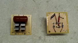
Assembled and tested another sub-assembly, this time the rectifier boards for the driver B+. They contain the rectifier bridge (four Cree 1200V Schottky diodes) and an RC snubber. Works as planned.
.
By the way, after that picture was taken I went back and removed the extra solder pads between the high-voltage points of the bridge and gave the board a coat of conformal coating, just to seal it all up and be sure nothing was close enough to arc. Just a note for completeness sake...
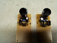
Today I completed the DC heater boards for the 6E5P driver tubes. I mirror imaged them so the wiring will be optimum in both the left and right amps. It's a simple circuit with a 2A, 40V Schottky bridge (SMD) feeding a 10,000uF cap, followed by an LM1084 adjustable LDO regulator. The regulator has 1000uF across the output and 56uF to ground from the adjust pin. I also added an RC snubber across the AC input (20nF C0G ceramic cap and 330ohm resistor).
This circuit is able to easily get 6.3VDC from 6.3VAC, in fact I can get up to 7.5 VDC max, so I can use the 6.3VAC winding on the 369KX transformer. At 6.3VDC I measure only 3mV AC, so it should be a nice quiet supply. I'll have some .1uF caps to ground at the tube heater pins to further reduce any noise from the regulators.
The other half of the two boards will carry a similar circuit (12V) for the 833 cooling fan power, but it will be a little simpler, with no AC snubber or adjust pin caps to ground...after all it's just to power the fans.
Attachments
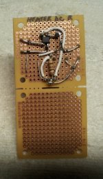
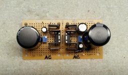
Here's a snapshot of a completed board, with both the 6E5P heater 6.3VDC supply and the 833 cooling fan 12 VDC supply. The fan supply is the simpler looking one.
Having these two boards as compact as possible helps me to fit all the rest of the BIG stuff inside the chassis. This combo board will tuck nicely into the side of the amp chassis.
Having these two boards as compact as possible helps me to fit all the rest of the BIG stuff inside the chassis. This combo board will tuck nicely into the side of the amp chassis.
Attachments
Hi Unison845,Hello Matthias,
Thanks for the response.
I built a pair on 833 amp about 10 years ago, I dont listen to them anymore since I have few other amp to play with, but I am interested in upgrading them with better output transformer.
A few years ago a friend bought a pair of 1642 SE (about $600/pr), they are OK but not great, since it has peaking at 20Khz, and low frequency distortion when loaded over 150ma.
You sine wave waveform looked surprisingly good, that's why I am interested to see the frequency response across the spectrum for your amp to see if there is any issue with the output transformer.
Did you buy the HP 8903 audio analyzer? I have one myself and it is a great instrument.
Please post your amp frequency response when you have a chance to measure it.
Thank you.
Quote:
Originally Posted by Mister Ed
Hi,
@ Unison845
No, i did'nt do any plot...(I'm plottintg with my ears
The 1642SE is a good OPT but you should'nd use the 8Ohm tap.
There is a lot of drop over 8kHz... the 4Ohm and the 16 Ohm taps are OK.
As you can see in my pictures it is very linear at the 16Ohm tap. Normaly the 1642SE has a Raa of 5kOhms, so if you use it with 8Ohm speakers at the 16Ohm tap, it works very well - with a Raa of 10kOhms seen at the 833...
Hope that my HP-Audio Analyzer will be delivered at this week, so I can do a lot of more measurements...
Greetz, Matthias.
yesterday my HP 8903B arrived...
Because I don't have an old computer (Windows 98) and no HP-IB-interface, I made a "manual plot"...
Attachments
Thanks Matthias,
Just like what I expexted, but then for the price it is not a bad deal.
Just like what I expexted, but then for the price it is not a bad deal.
Hi Unison845,
yesterday my HP 8903B arrived...
Because I don't have an old computer (Windows 98) and no HP-IB-interface, I made a "manual plot"...
Hi Unison845,
Ok, it's not perfect but +0,05/-0,7dB is lower than the specs for this OPT (-1dB for 20Hz-20kHz) and the -0,7dB notch is between 16 and 18kHz.
I'm 44years old...so I can hear no frequency more than 16 kHz (may be intermodulation products) ...-0,7 dB is nothing...the most (and also very good and expensive speakers) are specified with -3dB and -6dB(!)
Why should I pay 2000€ more per channel when I can't hear a difference?
I'm happy with my mono-blocks as they are.
(btw. I have more than this one midlife crisis...an AMG Mercedes and a Crossfire are hard to feeding...)
@tomchr
Thank You very much for this advise...I was ordering a GBIB-USB from Prologix
Matthias
Ok, it's not perfect but +0,05/-0,7dB is lower than the specs for this OPT (-1dB for 20Hz-20kHz) and the -0,7dB notch is between 16 and 18kHz.
I'm 44years old...so I can hear no frequency more than 16 kHz (may be intermodulation products)
...-0,7 dB is nothing...the most (and also very good and expensive speakers) are specified with -3dB and -6dB(!) Why should I pay 2000€ more per channel when I can't hear a difference?
I'm happy with my mono-blocks as they are
.(btw. I have more than this one midlife crisis...an AMG Mercedes and a Crossfire are hard to feeding...
)@tomchr
Thank You very much for this advise...I was ordering a GBIB-USB from Prologix
Matthias
Hi Matthias,
Yes, for the price it is hard to beat the Hammond.
Tomchr,
I was planning to buy the prologix too, I was wondering what software can you use to plot the curve from 8903, or hp network and spectrum analyzer.
Yes, for the price it is hard to beat the Hammond.
Tomchr,
I was planning to buy the prologix too, I was wondering what software can you use to plot the curve from 8903, or hp network and spectrum analyzer.
Hi Unison845,
Ok, it's not perfect but +0,05/-0,7dB is lower than the specs for this OPT (-1dB for 20Hz-20kHz) and the -0,7dB notch is between 16 and 18kHz.
I'm 44years old...so I can hear no frequency more than 16 kHz (may be intermodulation products)
Why should I pay 2000€ more per channel when I can't hear a difference?
I'm happy with my mono-blocks as they are
(btw. I have more than this one midlife crisis...an AMG Mercedes and a Crossfire are hard to feeding...
@tomchr
Thank You very much for this advise...I was ordering a GBIB-USB from Prologix
Matthias
OK, I'd like some help thinking through the power dissipation and heat sinking requirements of the AOT1N60 mosfet driver. Here's the way I figure it.
Looking at the graph in post #23 of this thread, at full power the circuit is pulling grid current about 1/3 of the time. Assuming the worst case scenario of a square wave of grid current at 180mA plus the 32mA DC plate current for the 6E5P, the average current would be:
.67*32mA + .33*212mA = 91.4mA
Average power dissipation at full power would be:
91.4mA*(400V-216V) = 16.82W
The AOT1N60 is rated for 41.7W at 25C and derated at 0.3W/C to 31.2W at 60C. I'm hoping to heat sink the mosfet sufficiently to keep it at 60C, so the 31.2W figure would be applicable.
So, for a sanity check, does this look about right? Sounds like the AOT1N60 should survive, correct?
If not, I could upsize to the AOT2N60, which is rated at 53W at 60C, but which has twice the capacitance of its smaller brother.
Thoughts?
- Home
- Amplifiers
- Tubes / Valves
- The Midlife Crisis - My 833C Amp Build