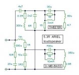
Hit the return button and the darn thing posted !
Hi Ingrast.
I note that the LD6C has no impedance compensation about the mid range.
This is the approximate I have used for the 'Ariel' loudspeaker.
Two choke resistances included, they are not separate series resistors.
Cheers ....... Graham.
Hi Ingrast.
I note that the LD6C has no impedance compensation about the mid range.
This is the approximate I have used for the 'Ariel' loudspeaker.
Two choke resistances included, they are not separate series resistors.
Cheers ....... Graham.
Attachments
Graham Maynard said:Hi Lumanauw,
I am a little tired at the moment so will answer your enquiry soon.
David,
Maybe I can liven up the discussion a bit by stating that it is my conviction that First Cycle Distortion as defined by Graham doesn't exist because his simulations are based on non-existing audio signals.
Jan Didden (wearing his flak jacket & ducking)
janneman said:
David,
Maybe I can liven up the discussion a bit by stating that it is my conviction that First Cycle Distortion as defined by Graham doesn't exist because his simulations are based on non-existing audio signals.
Jan Didden (wearing his flak jacket & ducking)
...and there i was thinking Graham didn't 'do' simulation....and 'books'....and only dealt with 'hands-on' stuff...

http://www.diyaudio.com/forums/showthread.php?postid=669224#post669224
mikeks said:NNNaahhh....i reckon if it aint broke why fix it....
If ever gets broken, I demand first priority to fix her ....
Rodolfo
Graham Maynard said:Hit the return button and the darn thing posted !
Hi Ingrast.
I note that the LD6C has no impedance compensation about the mid range.
This is the approximate I have used for the 'Ariel' loudspeaker.
Two choke resistances included, they are not separate series resistors.
Cheers ....... Graham.
I noted something going on in the graphs. Anyway the idea is to put all the "back EMF" talk on some more down to Earth footing by way of an example, not designing an ultimate system.
Anyway I dislike passive crossovers, will never design or build one.
Rodolfo
Hi George,
My hopes dashed. I wondered if there was a new 'dumper' on the horizon.
Hi Lumanauw,
Re Post#116.
Surely TIM is an internal amplifier effect related to input, whether with or without NFB, and can predictably arise at high slew, even with a purely resistive load, though be worse due to reactive loading.
Back-EMF is an externally generated but coincidental impingement and can arise at any frequency and not be directly related to input.
It is possible to reduce the effect of back-EMF by inserting a series output resistor that is much higher than the amplifier's output impedance.
John Lindsley Hood used a series 0.22 ohm resistor about thirty years ago. If the amplifier can have a very low NFB loop generated output impedance then the resistor establishes a non-reactive protection ratio against back-EMF, and interface distortion is reduced. Of course the loudspeaker circuit damping is then degraded, and this might not be acceptable with some loudspeakers/situations.
It is possible to use a series output fuse to do exactly the same job, though obviously this should be selected, specified, check measured and soldered-in, or an optimum loudspeaker lead resistance value could be specified. Even better, every separate driver circuit lead could have a separate optimum resistance back to the output terminals for single amplifier operation.
Maybe the insertion of a humble 0.22 ohm series output resistor could be used to test an amplifier/cable/loudspeaker combination for output interface induced distortion. If the sound remains unchanged then the amplifier has not been reacting to back-EMF.
Hi Mauro,
I must admit that I am not sure that I fully understand your Post#117 and 118 graphs.
I am assuming that the brown trace is amplifier output amplitude, and the blue trace the amplitude measured at the 'loudspeaker' side of a selected series connected output resistor.
When the series resistance is low the amplifier could be directly countering back-EMF. The phase shifted back-EMF combined with internal non-linear amplifier phase shift is leading to a necessary increase in output to satisfy input/NFB loop sensing.
As the resistor value increases, the load Q decreases, and the magnitude of reactive impingement decreases; thus the necessary internal and fractionally phase shifted error correction also decreases.
Hence the brown amplifier response becomes more linear as the reactive nature of the back-EMF is reduced via increasing series resistance, but the blue load voltage shows more load reactance induced loss.
Similar responses can be seen by expanding the amplitude traces of a simulated amplifier driving a simulated loudspeaker, and there can be several peaks/troughs through the audio spectrum.
This is one mechanism for interface distortion to arise, and high NFB generated damping is not always the solution when the amplifier's internal stabilisation network(s) render the output terminal reactive wrt ground.
Hi Jan,
(Only flak jacket; is it waterproof ?)
Before I reply to Lumanauw, what test signals are genuinely audio ?
__________________________________________________
I am hoping that this thread too is not now going to be actively degenerated by irrelevent and deliberately negative postings !!!!!
I personally enjoy Lumanauw's questioning and read Mauro's work with genuine interest.
Cheers ......... Graham.
Graham Maynard said:[snip]Hi Jan,
(Only flak jacket; is it waterproof ?)
Before I reply to Lumanauw, what test signals are genuinely audio ?
__________________________________________________
I am hoping that this thread too is not now going to be actively degenerated by irrelevent and deliberately negative postings !!!!!
I personally enjoy Lumanauw's questioning and read Mauro's work with genuine interest.
Cheers ......... Graham.
Hi Graham,
First of all, I hope you do not consider my comment as "actively degenerated by irrelevent and deliberately negative postings ". I try to comment on the subject matter, not on the person!
I don't think I can give a clear and all encompassing definition as to what are genuine audio signals. But, as is so often is the case in engineering and science, it IS possible to have an opinion on a specific signal whether it is 'genuine audio'.
If I interpreted your very extensive article series in EW correctly, the test signal you used is a suddenly starting signal at a level other than zero. That causes a very fast transient right at the start, in theory infinitely fast. Of course that gives rise to all kinds of anomalies because no amp can cope with such a transient. You call these anomalies (or some of it) First Cycle Distortion (FCD). In my view, if the signal would be bandlimited, the fast transient would all but disappear, along with the FCD.
At least one commenter in EW stated that with an input bandlimiting (as will always be the case, if not the filters and bandlimiting of the source), FSD would all but disappear. To which you replied: "excuse me, since when do we listen to filters?" or words to that effect. So, you choose not to address the perfectly valid remark, but keep on using a test signal that in practise will not appear at the amp input.
Jan Didden
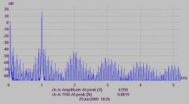
Hi Graham, in your post#129 you have exposed exactly my conclusions, is as answered to lumanauw that to me.
I am able only integrate the reasoning with a little series of demonstrative measures.
The setup is the usual trafo+filter@2.4Vrms of the firsts (IMD) graphs, but the measure is relative to 4.5Vrms 1khz ( rather than 3Vrms ). The first thing that it is note is an increase percentage of IMD with the grow of the signal of entry ( but this is obvious )...
P:S: No problem for new "d u mping structure" ( Only after showing serve to improve this problems)
Attachments
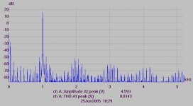
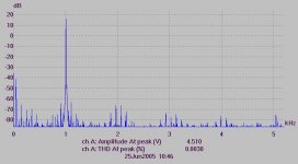
But the "secret" ( believe ) to the proposed problems by Graham is this: if you notices the encircled to High and mid NFB have the first signs of IMD to about -25dB from 50Hz fundamental . If we increase the DF reduce all altogether. The graph of JLH has a difference of about -40dB. This means that to parity of DF the circuit JLH is a lot of more linear ( immune from back-EMF ).
Ciao
Mauro
Ciao
Mauro
Attachments
Hi Mauro,
There have been long running 'debates' (to put it mildly) ;-
1) based upon established ac theory - that series output chokes do no more than fractionally reduce tweeter drive due to an inductive potential divider effect;
2) based upon the findings of some amplifier designers - that series output chokes degrade reproduction.
Nelson Pass was one of the first to commit this to print, I investigated this in my article and illustrated its electrical possibility when the driving amplifier has a very low output impedance.
1) precludes the possibility of any suddenly starting wave,
2) is the audible effect of a suddenly starting wave - a hf audio transient.
(I am repeatedly informed that I am wrong to start waves suddenly when examining amplifier response in order to *minimise* the distortion effects that could be induced by a suddenly starting wave.)
I wonder what your Post#118 traces would look like with a typical say 5 to 10uH series output choke in place of that resistor, and then an additional analysis like Post#133 ???
Your findings in relation to the better back-EMF performance of the JLH had long ago been noted here via my first cycle forward and reverse excitation examinations, which I suggested that diyAudio members should try for themselves some time ago. However I became the butt of some mindless postings, so I just went back to my soldering iron.
Hi Jan,
Thank you for exampling your question.
( I am sure EW readers wonder why I did not continue answering their letters -
EW failed to make the donation to charity as agreed prior to submission and as stated during publication.)
You are mentioning my response to the letter of Mr Bailey Ph.d. M.Sc. F.I.E.E. in Oct 2004, and this arose before I had broached my examination of an amplifier's first cycle capabilities.
Mr Bailey later wrote again at length to claim that established theory was being ignored, and yet he did not actually challenge my suggestions, nor use any established theory to show that anything I had written was wrong.
Mr Bailey was wrongly suggesting that my reports of spiky distortion products were due to my use of suddenly starting waves, but I had reported hearing a 'glassy' solid-state or indistinct sound on many amplifiers in real life. My early simulations did not show any spikes related to reproduction, though an error trace (difference voltage for low impedance amplifiers with and without a series output choke) did of course appear as a spike, but as I wrote - that is the differential loss, not the actual output.
My reply was a comment on the sound of filtered audio, as per SSB and CW filters. It is possible to have extremely low distortion filtered audio, but these examples are not musical, so where do we draw the line at suddenly starting waves ?
What about a triangle, cymbal, or rim strike, and at the lower extreme - a kick drum or picked bass guitar string? These waveforms do start suddenly.
Ever had a CD player lose data?
Some amplifiers just stop and start reproduction, others click (hf) and output a dc (lf) component. I would venture to say that the difference in performance will not show up during continuous wave testing, but it will if the amplifier's first cycle (suddenly starting) response is captured.
And amplifiers themselves can also produce a suddenly starting output from filtered input - due to overpowering loudspeaker generated back-EMF (especially in professional situations) - when their NFB loop control of output devices is momentarily exceeded.
Hi Lumanauw.
I have not finished these FCD discursions yet. It reveals other problems that steady sinewave investigation cannot show, but alas I am not presently gifted with sufficient time.
If anyone believes I am wrong to artificially examine amplifier operation in this way, then please understand that squrewave and slew rate testing are no more correct either, and that undistorted sinewaves are not at all musical.
Cheers ......... Graham.
Suddenly starting waves
Place a comparartor followed by S/H at the feedback summing node, so it will only store peaks that exceed the amp linear operating region.
Load the amp with a real speaker, drive the amp with any desired program, taking care to avoid clipping (clipping will exceed the amp's linear operation range).
If the S/H shows any output, it is because the amp was driven out of the linear operating range by a sudden starting wave; otherwise no.
Graham Maynard said:[snip]Hi Jan,
Thank you for exampling your question.
( I am sure EW readers wonder why I did not continue answering their letters -
EW failed to make the donation to charity as agreed prior to submission and as stated during publication.)[snip]
Cheers ......... Graham.
That is most unfortunately, and doesn't seem fair. Apart from the disagreement one has, you DID a large amount of work and filled many pages for EW, they should rightly compensate you or your charity
Graham Maynard said:[snip]My reply was a comment on the sound of filtered audio, as per SSB and CW filters. It is possible to have extremely low distortion filtered audio, but these examples are not musical, so where do we draw the line at suddenly starting waves ?
What about a triangle, cymbal, or rim strike, and at the lower extreme - a kick drum or picked bass guitar string? These waveforms do start suddenly.[snip]
Kick-drums or other instruments starting 'suddenly' is relative. The physical vibrating material CANNOT start from rest to whatever speed in zero time. It will start much more gradually than the suddenly starting sines you show in your article. I understand from other posts that artificially generated sounds llike those produced by electronic means or by DJ's can contain heavily clipped and steep signals, but I don't think in such a situation one would worry a lot about FCD.
[snip][snip]And amplifiers themselves can also produce a suddenly starting output from filtered input - due to overpowering loudspeaker generated back-EMF (especially in professional situations) - when their NFB loop control of output devices is momentarily exceeded.
Well, that keeps coming up again and again. Where is that documented? EMF, even if it IS 'overpowering', has the same physical basis as the 'suddenly starting kick drum'. It is produced by a vibrating cone, and is much less 'sudden' then we think. Why should that 'overpower' an amp nfb loop???
[snip]Thank you for exampling your question.[snip]
Not to split hairs, but I did neither. I was stating an argumented disagreement....
Jan Didden
Hi Graham, other material of study.
You have to excuse me, but have noticed to have a opinions in common with you, but have not read the publications of which speaks. My strategy of base is that to analyse very valued amplifiers ( and of easy construction ) to establish like parameters is the sub-judice of the good result. Here because I often use JLH in the tests ( by the way I use the "base" version without Rout but with EL. cap. output ).
In connection with the output choke , sincerely I prefer doesn't them use, for the sub-judice that you have studied you and because it is a EMI generators. If find the time is able try to do the tests that propose me.
In connection with the "theories" controversies, creed that it has to be space completely the hypothesis, the main point is argue from it.
I concern the EMFs, I believe that are a series of "indirect" phenomenona. I think that is an error gather only on the amp. This THD are a lot of more little of that of the loudspeakers, and in the back-EMF phenomenon not consider gives a complex it dynamics that would define ( with my very bad English ) " shape Back -EMF " that is instigated in the amp+cable+spk system, and I believe in degree to attenuate or accent the THDs ( and IMDs ) characteristic of the speakers. Affair remembers that all the phenomenona observed in our test have a "temporal sequence": electric solicitation-enliven mechanic- back generation-( speaker THD + back-solicitation) amp EMF-electric reaction -mechanical shading (final conditions)...
Ciao
Mauro
Hi Jan,
You have stated the obvious, ie. mass/energy limitations that relate equally to instruments/microphones/loudspeakers as to all matter.
If you want a car to ride smoothly you develop/test it over bumpy test tracks that are worse than normal roads.
If you want an amplifier that is not going to be caught out by transients, then you check out its circuit behaviour with transients, and ensure a greater capability than anything it might be called upon to handle.
If you are developing and studying several different amplifier circuits then it makes sense to test them all in the same way. Yes a suddenly starting 10kHz simulation is unreal, but some of my test circuits handle such a first cycle well when compared to most others, so how can it be wrong for me to check them out in this way, and how can it be wrong for me to suggest that others might find such testing illuminating in a way possibly not considered before simply because it is known to introduce unrealistically sudden voltage change; also a way that is still being actively discouraged ?
I am still waiting for someone to show me why such circuit testing is actually wrong !
Actually if I had followed your reasoning, and the methods I had grown up with, I would not be constructing the circuits I presently am !
If there are no suddenly starting transients, then why do loudspeaker manufacturers impulse test composite loudspeaker systems with the fastest pulse they can generate, instead of a filtered hf step function from an audio amplifier (which is what they will realistically end up being driven by anyway) ?
Jan. Have you never heard an amplifier being overpowered by bass driver transduced back-EMF through a whip like build up of cone/cabinet/air-spring energies at less than maximum output voltage clipping amplitude ?
An amplifier can become momentarily reverse driven by what is effectively a suddenly starting wave. I have observed it, but I don't know how I can prove it to you !
It is a rare and extremely dynamic event due to a combination of music/amplifier/loudspeaker, but still indicates a problem that should never arise.
If we check how amplifiers behave when reverse driven, and especially any leading reverse edge induced bias/stability (first cycle) effects that could induce a 'crack-like' re-settlement sound, pop output devices or lead to driver destruction, then our amplifier designs could be more reliably capable.
I am not wanting to split hairs or argue with you personally, for I already understand your point of view and could also put up all of your arguements, however I know from experience that the simulation of forward and reverse suddenly starting first cycle responses at 10kHz has helped in my development of circuits that provide more accurately detailed hf audio reproduction.
Hi Mauro,
No-one has to excuse you, you are doing well.
Yes I agree with your 'temporal sequence' description, though it does of course act continuously with the error magnitude at any frequency being amplifier design dependent; ie. amplifiers will have thresholds beyond which they become worse, I suppose like inter/cross-mod thresholds in radio receivers, and it is likely that amplifiers having lower open/closed loop hf phase change (which shows as comparatively better first 10kHz cycle reverse injection control) and class-A biasing will be more immune.
Cheers ......... Graham.
I remember the basic physics from high school. Energy is eternal. It cannot be made disappeared, even 0.0000001watt. It can change to other energy form, but cannot be made disappeared.
One of the enery storage system is steel spring. If we push or pull the spring from its 0 excursion, it will keep some energy. It will try to release the energy inside it to get back to 0 excursion again.
In steel spring the energy given will be returned back in the same way as it is received by the spring, as movement or distance from 0 excursion.
In speakers, energy is given by voltage, changing to speaker excursion, it changes to sound energy, and the residual will change a little to heat (in voice coil and magnet), but I think majority of residual (after changing to sound energy) energy stored during excursion will be given back as "back EMF" which the amplifier has to "receive", like it or not.
In the "energy return" process, the speaker's excursion is converted back to voltage at the speaker terminals.
Back EMF existed, because energy is eternal. No one can make or make even very little energy disappeared. It can change form (usually to heat), but in some storage system (like steel spring) it will be returned back the same way it is received.
If it existed, the next is how to make an amplifier that can deal perfectly with this back EMF.
Walt Jung has a very interesting article. He asked, how many inputs does 1 opamp has? Many person thinks it is only 2 inputs, the inverting and non inverting input.
But he stated that voltage points are also input points for opamps. Why, because if we change the condition at voltage points, it will affect the output too.
This is the question. Is the output node of the power amplifier forming another input for the amp system or not. In feedback sytem, YES, because the signal at the output node will be feeded back to the whole system by feedback system.
So, back EMF is another "distoriton source" for feedback power amplifier, even it comes at the output node. Back EMF is giving "not-music-related" energy at the output node, that the amp has to synchronize with signals at the inputs and amps output. (whew, how difficult it is tobe the amplifier )
One of the enery storage system is steel spring. If we push or pull the spring from its 0 excursion, it will keep some energy. It will try to release the energy inside it to get back to 0 excursion again.
In steel spring the energy given will be returned back in the same way as it is received by the spring, as movement or distance from 0 excursion.
In speakers, energy is given by voltage, changing to speaker excursion, it changes to sound energy, and the residual will change a little to heat (in voice coil and magnet), but I think majority of residual (after changing to sound energy) energy stored during excursion will be given back as "back EMF" which the amplifier has to "receive", like it or not.
In the "energy return" process, the speaker's excursion is converted back to voltage at the speaker terminals.
Back EMF existed, because energy is eternal. No one can make or make even very little energy disappeared. It can change form (usually to heat), but in some storage system (like steel spring) it will be returned back the same way it is received.
If it existed, the next is how to make an amplifier that can deal perfectly with this back EMF.
Walt Jung has a very interesting article. He asked, how many inputs does 1 opamp has? Many person thinks it is only 2 inputs, the inverting and non inverting input.
But he stated that voltage points are also input points for opamps. Why, because if we change the condition at voltage points, it will affect the output too.
This is the question. Is the output node of the power amplifier forming another input for the amp system or not. In feedback sytem, YES, because the signal at the output node will be feeded back to the whole system by feedback system.
So, back EMF is another "distoriton source" for feedback power amplifier, even it comes at the output node. Back EMF is giving "not-music-related" energy at the output node, that the amp has to synchronize with signals at the inputs and amps output. (whew, how difficult it is tobe the amplifier
)- Status
- This old topic is closed. If you want to reopen this topic, contact a moderator using the "Report Post" button.
- Home
- Amplifiers
- Solid State
- The many faces of distortion