Hi Rodolfo,
Yes your Post#81 and notes relating to IC loading struck home with me, and it is good to see a wider appreciation of NFB loop induced problems.
When I wrote my notes for Electronics World in 2003 I felt like I was putting my neck on the block for broaching back EMF / reverse amplifier behaviour, and then whilst it was being published I though " Oh heck, What have I done ? ".
I deliberately wrote everything from an observational basis, and yet I still received challenges as if I was abandoning theory.
I don't believe you are wrong to state that a resistive load may be used for this forward/reverse testing, however, doing so will immediately limit the test loading when compared to real-life usage. Real-world amplifiers are obliged to drive simultaneously against more than one back-EMF; thus using a resistor immediately limits the test to one alone, where a reactive load could measure effects due to two without need for extra sources, and more should be possible with storage scope observation of transient responses.
Did not Otala many many years ago, and then D Self about ten years ago, show that transient output currents could be up to six times those observable with sine/resistor loading ? No reverse driven resistor load could approach this level of conduction, as indeed nor could one single reactive load circuit.
Our problems are caused by back-EMFs which as yet have not been 'precisely' mimicked.
Hi Mauro,
I note you use the term 'real dumping'.
Is this by any chance 'real time' current 'dumping' without the clever bridge that is used by Quad (a bridge that introduces fractional delay)?
Posts#100+101 downloaded as I send this, but not yet studied.
Cheers ......... Graham.
Analysis of the distortion caused by back EMF
Mauro:
Let me first voice my apreciation for all your efforts.
I know first hand things are easier said than done, and that you have put several hours hooking up test gear, solving glitches, getting and checking measurements, and drafting results for us to enjoy.
Unfortunately I have serious drawbacks to point out in this last series of measurements.
The square wave signal you are using for the DUT at 3225 Hz is a cute way to put together several test signals at once, but since they are harmonicaly related, you cannot resolve during the test how much of the measured signal (at second and higher harmonics) is original and how much is distortion products from the fundamental due to the load setup. The same applies for the higher tones, for example the fourth harmonic if measured, should include part original signal, part forth harmonic distortion of fundamental, and part second harmonic distortion of the original second harmonic and so on.
Second and related as will be seen, you are keeping the paralell resonator at 1 KHz intended in the Hiraga test to isolate (at 1 KHz) the DUT from the 50Hz source.
This isolation only holds at 50Hz, meaning that when you apply the 3225 test signal, what the DUT sees at its output is the intended nominal 8 ohm load in paralell with a 6.2 ohm resistor in turn in series with (basicaly) a 3.3 uF capacitor and whatever impedance transformer T1 reflects from the variac. It goes without saying that this impedance is basicaly unknown and of course frequency dependent.
What all this means is that what you are actually measuring indirectly is the DUT output impedance at different frequencies, and at a lower and complex reactive load. This has consequences with regard to amplifier behavior, eventually depending on cases increased distortion which as indicated formerly clouds the actual measurements for they cannot be distinguished from the input signal itself.
Again, I am sorry to have to flag this problems. I think you have the drive to produce important results, but you strayed in this last case from the former goal of assesing EMF impact on IM, that was the original Hiraga setup goal.
Rodolfo
PS
With regards to the added 0.27 ohm series resistor for the GC setup, any series resistance will contribute to make the DUT load impedance a little larger. I must confess the graphs do not show a substantial improvement, something to be expected given the low resistor value.
Graham Maynard said:.....I don't believe you are wrong to state that a resistive load may be used for this forward/reverse testing, however, doing so will immediately limit the test loading when compared to real-life usage. ....
Graham:
Sure enough reactive loading is a reckoned problem but probably not given enough coverage as other topology related issues.
The problems with testing with actual reactive loads are twofold.
On the one hand, nobody can know in advance how a certain amplifier will be used (drivers, crossovers etc.) so there is no such thing as a standard reactive load.
Second, I guess the Hiraga setup was cleverly devised to isolate things, that is, to have control on the offending EMF in magnitude and frequency, while the amplifier sees a nominal resistive load. While of course not all inclusive, this test may shed light on IM mechanisms and suggest corrective actions.
I for myself have had my attention raised not only on the importance of as low as attainable effective output impendance, but probably more importantly to the capability to drive a virtual short circuit, that is an impedance perhaps an order or magnitude below nominal without undesirable effects, to account for what actual speaker loads can display under certain circumstances.
Rodolfo
Hi, Janneman,
Thanks for the schematic. It is quite a high OL gain amp with many stages.
Hi, Mr. Maynard,
Yes, John Curl said exactly the same thing. Transient current while headed to real speaker system can dip to very large current (because the speaker impedance dips to very low value). This cannot happen with R loading only. Not to mention voltage-current phase change while headed to reactive load.
I imagine every speaker don't like to change its position (like a steel spring). It only likes to sit at 0 excursion, like in its normal position. While the power amp forces the speaker to excursion, the speaker itself will react by sending back EMF to get back to its 0 excursion.
The amp have to handle this "reaction", and in feedback system this will add to the transfer function, usually resulting in high-order artifacts. How far this goes, depends on how many stages the power amp has. JLH has very few stages, it will sound differently than an amp that has many stages, when headed to loudspeaker load.
Thanks for the schematic. It is quite a high OL gain amp with many stages.
Hi, Mr. Maynard,
Did not Otala many many years ago, and then D Self about ten years ago, show that transient output currents could be up to six times those observable with sine/resistor loading ? No reverse driven resistor load could approach this level of conduction, as indeed nor could one single reactive load circuit.
Yes, John Curl said exactly the same thing. Transient current while headed to real speaker system can dip to very large current (because the speaker impedance dips to very low value). This cannot happen with R loading only. Not to mention voltage-current phase change while headed to reactive load.
I imagine every speaker don't like to change its position (like a steel spring). It only likes to sit at 0 excursion, like in its normal position. While the power amp forces the speaker to excursion, the speaker itself will react by sending back EMF to get back to its 0 excursion.
The amp have to handle this "reaction", and in feedback system this will add to the transfer function, usually resulting in high-order artifacts. How far this goes, depends on how many stages the power amp has. JLH has very few stages, it will sound differently than an amp that has many stages, when headed to loudspeaker load.
Hi Lumanauw,
Yes an amplifier has to 'handle' composite loudspeaker reaction.
Thus every series/parallel capactitance/inductance connected to an amplifier's NFB loop controlled output terminal has a (delayed) effect upon amplifier output.
Some cables can pose problems to some amplifiers, and some crossovers are less reactive than others.
The worst effects are due to delayed charging, electrical or electromechanical (C via L and airspring via voice-coil), with sudden energy releases occuring within lead/load circuit dependent time frames. Under certain (unpredictable) music driven conditions these releases can combine, and always after a delay following their initial independent transient energisations.
Thus phase linear resistor/steady sine-wave testing remains of very limited use, though suddenly starting waveforms can be used to illustrate transient system behaviour, or lack thereof.
Yet still there are some of old formal training who claim that such amplifier study 'breaks established rules'; the very rules that have left us where we are because they have not been conducive to genuine progress !!!
My own approach was to simulate an amplifier's first cycle behaviour for a suddenly starting 10kHz sinusoid; forwards and reverse.
I do not need to be told that this method breaks established rules, but it so clearly illustrates that an amplifier that has been optimised for minimum forward thd performance, becomes degraded in countering back-EMF, whereas one having a good reverse characteristic can still be made to have an acceptable forward performance, even if it is then not regarded as being a top class performer via thd analysis alone.
You mention the number of stages.
Yes, the more there are - the greater the propagation delay that must be introduced to ensure stability.
The greater the stabilising delay - the worse the back-EMF (reverse) control, because the amplifier becomes internally inductive. The amplifier's output impedance (provable via long established NFB theory) becomes another separate component of the output circuit; it develops a fractional series voltage that is related to load reactivity and not with signal input or intended loudspeaker output.
High NFB - very low internal error voltage, but error likely to be in quadrature with back-EMF above 1kHz.
Low phase shift design - low NFB delay - low error - error coherent with back-EMF - minimal quadrature induced interface products.
Apologies for rambling on.
Cheers .......... Graham.
lumanauw said:[]snip]I imagine every speaker don't like to change its position (like a steel spring). It only likes to sit at 0 excursion, like in its normal position. While the power amp forces the speaker to excursion, the speaker itself will react by sending back EMF to get back to its 0 excursion.
The amp have to handle this "reaction", and in feedback system this will add to the transfer function, usually resulting in high-order artifacts. How far this goes, depends on how many stages the power amp has. JLH has very few stages, it will sound differently than an amp that has many stages, when headed to loudspeaker load.
Hi David,
The original statement of Matti Otala (and I assume by proxy by John Curl) was based on measurements of a specific speaker (YAHAMA N100 IIRC) with square waves with varying duty cycle. Because of that speacific signal, very large current pulses, up to 6 times the nominal value, were drawn from the amp. But, although interesting as an engineering exercise, it should be noted that these test signals will never be encountered in any music system. Their value for real life situations is often overstated, they basically have NO relation to music signals.
I also have a comment on the general trend of this thread. The original Hiraga article was limited to a specifc situation, with a specific test setup. Again, it may be argued that this is artificial. But I assume that Mr Hiraga's purpose was to show the very large differences between amplifier topologies. Now,one can of course make this test more complex, more wide etc, but I am afraid that that only increases the confusion because you are mixing up variables and parameters, as Rodolfo already noted above.
I think if we were able to find out what we need to do in an amp to pass this relatively simple test with flying colors, that would already be a major step forward!
Jan Didden
janneman said:
Hi David,
The original statement of Matti Otala (and I assume by proxy by John Curl) was based on measurements of a specific speaker (YAHAMA N100 IIRC) with square waves with varying duty cycle. Because of that speacific signal, very large current pulses, up to 6 times the nominal value, were drawn from the amp. But, although interesting as an engineering exercise, it should be noted that these test signals will never be encountered in any music system. Their value for real life situations is often overstated, they basically have NO relation to music signals.
Jan Didden
Hi Jan Didden,
I cannot agree with you that square wave with varying duty cycles have no relation to music signals. We have encountered various music signals created by professional DJ's which include flat out square waves in low frequency domains exhibiting high punch bass signals and they too draw large current pulses from the amp upto 5 times at least and when the amp is forced in to clipping the waves are something to SEE.
Moreover pro-DJ's usually clip the amps to little extent because clipping of some specific waves turned out as punching low-end phenomena.
We ourself test with these kind of real music signal along with speakers fitted with passive cross-overs which enable the amp to push as much as 4 times its normal current driving requirements.
May be this one is not going to satisfying you , i say this under the influence of pro-world in which amps have to encounter real world abuses. whereas in home HI-FI the user listens to its equipment in a more gentle way.......
regards,
Kanwar
Originally posted by Ingrast
What all this means is that what you are actually measuring indirectly is the DUT output impedance at different frequencies, and at a lower and complex reactive load. This has consequences with regard to amplifier behavior, eventually depending on cases increased distortion which as indicated formerly clouds the actual measurements for they cannot be distinguished from the input signal itself.
You are right. the tests that have performed have underlined practically the ability of interface on reactive load of the launch amplifiers, and not there are elements applicable to dividing the effects of the Back-EMF from that reactive. Among the other discovered have that a ground loop has given of the measures slightly alters.
The associations among sound and behaviour on reactive load staies valid, but am not associable ( perhaps ) directly to the behaviour with EMF.
This setup doesn't isolate the single problems and not me likes.
Praies you to understand my errors, because I expose the results of my bench practically on real-time, without the time to filtering in "scientific" way the data that draw.
Ciao
Mauro
Originally posted by janneman
I also have a comment on the general trend of this thread. The original Hiraga article was limited to a specifc situation, with a specific test setup. Again, it may be argued that this is artificial. But I assume that Mr Hiraga's purpose was to show the very large differences between amplifier topologies. Now,one can of course make this test more complex, more wide etc, but I am afraid that that only increases the confusion because you are mixing up variables and parameters, as Rodolfo already noted above.
How to be able you see from my answered to Ingrast I have the same doubt ( even if me am the principal sub-judice of the confusion ).
From departs mine wants clarify that doesn't interest me from define new setup of measure, or criticize the second-hand setup by other. I consider simply this thread a way to reason on problematic a few argued ( and this is happening ).
Ciao
Mauro
Workhorse said:
Hi Jan Didden,
I cannot agree with you that square wave with varying duty cycles have no relation to music signals. We have encountered various music signals created by professional DJ's which include flat out square waves in low frequency domains exhibiting high punch bass signals and they too draw large current pulses from the amp upto 5 times at least and when the amp is forced in to clipping the waves are something to SEE.
Moreover pro-DJ's usually clip the amps to little extent because clipping of some specific waves turned out as punching low-end phenomena.
We ourself test with these kind of real music signal along with speakers fitted with passive cross-overs which enable the amp to push as much as 4 times its normal current driving requirements.
May be this one is not going to satisfying you , i say this under the influence of pro-world in which amps have to encounter real world abuses. whereas in home HI-FI the user listens to its equipment in a more gentle way.......
regards,
Kanwar
Kamwar,
Yes I can appreciate the difference between home listening to more 'natural' music than the pro-world. (Although probably a lot of people listen to pro-music at home?). In that case the amp must be able to deliver those amps, I agree.
Jan Didden
mauropenasa said:
...
Praies you to understand my errors, because I expose the results of my bench practically on real-time, without the time to filtering in "scientific" way the data that draw.
Ciao
Mauro
Cheers Mauro.
It is not very frequent to find people willing to acknowledge observations after hard and dedicated work. Congratulations and keep on with the good job.
Rodolfo
Originally posted by Graham Maynard I note you use the term 'real dumping'.
Is this by any chance 'real time' current 'dumping' without the clever bridge that is used by Quad (a bridge that introduces fractional delay)?
Near observation. In fact I use this term to define the condition of real dumping ability of the amplifier with reactive load.
From a lot of interventions in this thread I am emersed the limits that a NFB system has in the comparisons of "non coherents" signals with the input. In my experiments has verified that with various techniques of internal compensation and external "power factor correction" (zobel & serie resistors modifies ( obviously ) much the linearity of the dumping.
Originally posted by Ingrast
With regards to the added 0.27 ohm series resistor for the GC setup, any series resistance will contribute to make the DUT load impedance a little larger. I must confess the graphs do not show a substantial improvement, something to be expected given the low resistor value.
To depart the fact that we have established that this setup defines more the linearity on reactive load that from EMF, the effectiveness of res. 0.27 ohm is underlined by the values of 3 and 5 harm measured first and after the reactive load. In first 2 graph ( no res ) the variation is of about 1 %. in the graph with R0.27 the variation is of 0.15 |max|. Naturally this is fruit of a general increase of the Rout, but the linearity improvment of the dumping are concrete. To get the same resulted without abdicate to the dumping, techniques more risky is had to use by the point of view of the final results...
P.S. I am happy that you understands my errors...
A little addition. I analyse all the Your interventions and when I have time looks for the opportunity to analyse Your theories in the reality. In particular, from the exchange among Graham and Ingrast have material of work for a lot of monthes...
Ciao
Mauro
Graham,
Hm, it's the moment of taking responsability..
As far as I can see, Mauro in this context is using the expression "dumping" while really he means "damping", as in DF. But I think he can not be blamed for this, [but me yes..] because it's a widespread [wrong] practice..
Pardon me, Mauro, we should have discussed this before..
And congratulations again for the good job!
Ciao, George
Originally posted by Graham Maynard
I note you use the term 'real dumping'.
Is this by any chance 'real time' current 'dumping' without the clever bridge that is used by Quad (a bridge that introduces fractional delay)?
Hm, it's the moment of taking responsability..
As far as I can see, Mauro in this context is using the expression "dumping" while really he means "damping", as in DF. But I think he can not be blamed for this, [but me yes..] because it's a widespread [wrong] practice..
Pardon me, Mauro, we should have discussed this before..
And congratulations again for the good job!
Ciao, George
Graham Maynard said:Did not Otala many many years ago, and then D Self about ten years ago, show that transient output currents could be up to six times those observable with sine/resistor loading ?
...Our problems are caused by back-EMFs which as yet have not been 'precisely' mimicked.
Cheers ......... Graham.
...are you sure DF had anything to do with it Graham...?
Have you read Otala's paper on the subject....?
Hi, Janneman,
Yes, if this thread has only 1 path to go, do not wander anywhere, maybe it will result in something good.")
But there are many things that has to be clear to be able to do it. Like this, I want to ask Mr. Maynard.
Mr. Maynard,
Until now I really haven't understand fully your concept about first cycle. Could you (re)explain about it in simple words?
About back EMF, I think it is treated like the way TIM is treated. In TIM there are 2 solutions. 1=do not introduce high signals to the system, if the system is not very good with TIM (put low pass at input) and 2=make system that can handle transients fast enough without clipping. Here we can include those fast signals/no LPF needed because the amp is able to handle it.
Putting non-feedback to the system is like solution no.1 for TIM above.
Making a very high feedback is like solution no.2 for TIM above, but how great we can make such a feedback system? High OL loop usually needs many gain stages, while like Mr. Maynard said, many gain stages will worsen things (while headed to real speaker load), while at first it is needed for solution.
I think it is difficult to handle back EMF with high feedback approach.
Yes, if this thread has only 1 path to go, do not wander anywhere, maybe it will result in something good.
But there are many things that has to be clear to be able to do it. Like this, I want to ask Mr. Maynard.
Mr. Maynard,
Until now I really haven't understand fully your concept about first cycle. Could you (re)explain about it in simple words?
About back EMF, I think it is treated like the way TIM is treated. In TIM there are 2 solutions. 1=do not introduce high signals to the system, if the system is not very good with TIM (put low pass at input) and 2=make system that can handle transients fast enough without clipping. Here we can include those fast signals/no LPF needed because the amp is able to handle it.
Putting non-feedback to the system is like solution no.1 for TIM above.
Making a very high feedback is like solution no.2 for TIM above, but how great we can make such a feedback system? High OL loop usually needs many gain stages, while like Mr. Maynard said, many gain stages will worsen things (while headed to real speaker load), while at first it is needed for solution.
I think it is difficult to handle back EMF with high feedback approach.
To clarify any affirmations done in my relationship ( and close this capitulates ), I do see the simulation of the conditions of my setup. On account of a ground loop non anticipateded, the instrumental analysis had the characteristics simulated in the graph ( " ground to power out..." ) while the situation on the load is that in top graph. When he speak of sign |+| make a report on me the conditions that are seen under...
Attachments
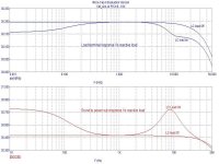
I conclude showing the simulation (lifelike) of the Rout joined situation( to clarify Ingrast the motives of her near perplexity ).
The condition that I saw is that of the graph under. Notice does it bewilders, that to the listening, the condition more linear is as that of the bot graph (with R=0.25ohm), while in theory to the load corresponds a greater excursion with the reactive load. This phenomenon would deserve a greater study...
Ciao
Mauro
Attachments
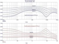
Full simulation
I am toying with the idea of making a full Thiele-Small simulation for a 2-way passive crossover.
It could be the LD6C studio monitor by Vance Dickason since I guess there is enough parameter data available.
It will take some time so if lucky, will be back in some days with it.
Rodolfo
I am toying with the idea of making a full Thiele-Small simulation for a 2-way passive crossover.
It could be the LD6C studio monitor by Vance Dickason since I guess there is enough parameter data available.
It will take some time so if lucky, will be back in some days with it.
Rodolfo
- Status
- This old topic is closed. If you want to reopen this topic, contact a moderator using the "Report Post" button.
- Home
- Amplifiers
- Solid State
- The many faces of distortion