The wire, down to, and wiring . . .
Hi tubelab! Thanks for the "secret sauce" recipes! I hope you're mending well.
@Printer2:
I still WANT the gain I HAVE when turned up to 10.
I had set things up so much to favor a great deal of distortion at high gain settings, that I couldn't get clean except at very low gain pot settings. This really limited the volume of clean coming out when the master volume was all the way up.
So I went back into the Radio Engineers Handbook and reviewed the material on pentode amps, coming across a graph showing a series of screen voltage curves superimposed on a graph with axes showing plate current and grid 1 voltage. Ah yes, approaching it that way! Choose the plate current and bias voltage FIRST, and then set the plate current using the screen voltage. Use a pot on the screen during development to find the resistance for the screen resistor that gives the right screen voltage! What a technique!
I needed a stronger clean signal, so I upped the plate load 150% and calculated the new plate current level that put one minus 62% of the B+ on the plate with that load. Then I chose my own grid bias to give the input to the tube more headroom. The reasoning was twofold: (a) I needed more clean gain (bigger RL) and (b) I needed clean to hang around longer as I turned the gain pot up, i.e., more headroom going into the stage before clipping, i.e., a bigger bias voltage. With the new values chosen I began to play with it, and tweak until I wasn't risking melting the screen grid (the 62% of Ebb across RL recommended book value for max gain wasn't going to work because it required exceeding the screen's rating. I ended up nearer to 50% of Ebb across the load at the sweet spot) and, voila!
It gives me clean for at least about 30% of the gain pot.
But now I've gotta get my upper end distortion back. Ah, no problem. I'll use a little DPDT switch and flip between clean at 30% gain, and fuzz grunge meltdown at 100% gain, flipping the bias resistor on one pole of the switch, and the screen resistor on the other to keep the plate current constant!
Or something.
Cause that is one ugly sound!
Let's see . . . can I fit another resistor under the hood here?
How about over there?
Hmmm, then again, how's it gonna look on the BOM?
Hi tubelab! Thanks for the "secret sauce" recipes! I hope you're mending well.
@Printer2:
I'm not quite sure if I know just exactly what you mean by this (which is why I did not reply earlier) but it is either the same problem I have now decided to address, or the opposite of it, I can't be sure.". . . want it clean I have to keep the input volume down to 1 or 2 ans still have the gain I want when turned up to 10."
I still WANT the gain I HAVE when turned up to 10.
I had set things up so much to favor a great deal of distortion at high gain settings, that I couldn't get clean except at very low gain pot settings. This really limited the volume of clean coming out when the master volume was all the way up.
So I went back into the Radio Engineers Handbook and reviewed the material on pentode amps, coming across a graph showing a series of screen voltage curves superimposed on a graph with axes showing plate current and grid 1 voltage. Ah yes, approaching it that way! Choose the plate current and bias voltage FIRST, and then set the plate current using the screen voltage. Use a pot on the screen during development to find the resistance for the screen resistor that gives the right screen voltage! What a technique!
I needed a stronger clean signal, so I upped the plate load 150% and calculated the new plate current level that put one minus 62% of the B+ on the plate with that load. Then I chose my own grid bias to give the input to the tube more headroom. The reasoning was twofold: (a) I needed more clean gain (bigger RL) and (b) I needed clean to hang around longer as I turned the gain pot up, i.e., more headroom going into the stage before clipping, i.e., a bigger bias voltage. With the new values chosen I began to play with it, and tweak until I wasn't risking melting the screen grid (the 62% of Ebb across RL recommended book value for max gain wasn't going to work because it required exceeding the screen's rating. I ended up nearer to 50% of Ebb across the load at the sweet spot) and, voila!
It gives me clean for at least about 30% of the gain pot.
But now I've gotta get my upper end distortion back. Ah, no problem. I'll use a little DPDT switch and flip between clean at 30% gain, and fuzz grunge meltdown at 100% gain, flipping the bias resistor on one pole of the switch, and the screen resistor on the other to keep the plate current constant!
Or something.
I hear you! Now I've gotta find a way to keep from over-saturating the reverb's input transducer when these hotter signals come out the other side of the master volume."And I thought I almost had this wrapped up."
Cause that is one ugly sound!
Let's see . . . can I fit another resistor under the hood here?
How about over there?
Hmmm, then again, how's it gonna look on the BOM?
So I went back into the Radio Engineers Handbook and reviewed the material on pentode amps..... Use a pot on the screen during development
I just pot a pot on the screen (1 meg).....and a pot on the plate (1 meg)....and a pot on the cathode (5K)...and a pot in seried with the cathode bypass (5K). I tweaked until I got what I liked and then....(the important part) try a bunch of different tubes, because they are all different. Yes, the screen voltage is the magic knob for plate voltage and the cathode resistor is for plate current. The plate resistor sets the gain.
Hi Printer2, love your work, using your ideas (also Tubekit, the Gimp, Tubelab et al).I have a problem with the low E string though. And I probably have to dump some gain somewhere.
I have been addressing this particular aspect by tweaking the bypass cap on the small signal pentode's screen. You have 1u I think. I have been as low as .047u for bass roll off.
Keep up the thread.
Regards to all.
JimG
Hi Gimp,Why not put a current source in the anode, pot in the cathode to adjust the anode voltage and pot in the Screen to adjust gain.
I do that when I'm breadboarding - and for my own amps - but I design for minimum numder of pots on anything that leaves the shed.
Switches are still fair game tho'
")
Regards
JimG
Why not put a current source in the anode...
Most pentodes become unstable when working into a current source. In ideal pentode is a constant current sink. Loading one with a perfect CCS wil make a bistable flip flop. Fortunately there are no perfect devices and a typical pentode can work into a CCS but the gain will be very high and somewhat nonlinear. Thermal drift and aging are big issues. A CCS in parallel with a resistor can make a good high gain stage, but the output impedance will also be very high. CCS loads work very good on triodes though.
There is some design information showing the use of pentodes with CCS's on Gary Pimm's web site.
pot in the cathode to adjust the anode voltage and pot in the Screen to adjust gain.......I do that when I'm breadboarding - and for my own amps - but I design for minimum numder of pots on anything that leaves the shed.
I wasn't advocating using pots in the finished product, just explaining one of my design methods. However having too many pots can make it impossible to converge on the right solution without the knowledge of what each one does, and how they interact. Put 2 or 3 pots on each of 4 gain stages and you will never get there. To get 4 stages right, connect up the first stage only and tweak it up with a scope, then add the second......
Hi Printer2, love your work, using your ideas (also Tubekit, the Gimp, Tubelab et al).
I have been addressing this particular aspect by tweaking the bypass cap on the small signal pentode's screen. You have 1u I think. I have been as low as .047u for bass roll off.
Keep up the thread.
Regards to all.
JimG
The screen bypass is 0.1uF, only so much resolution on the pictures from photobucket I guess. A couple more.
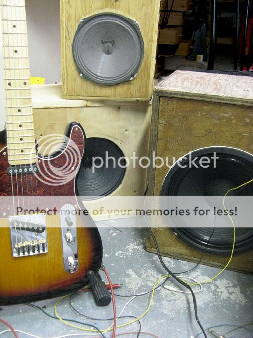
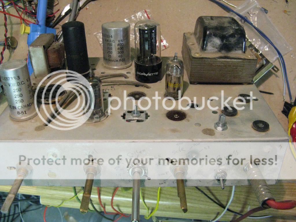
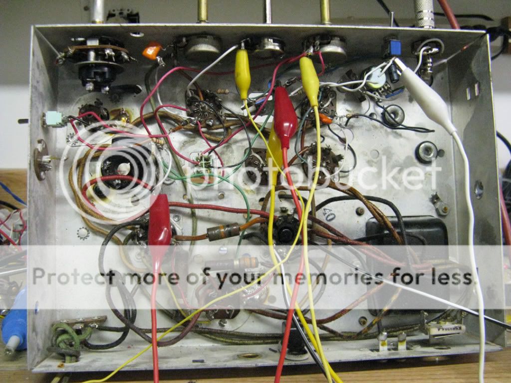
I used the 1.5M on the front for the screen, 5k cathode pot, resistance values pencled in on the front. 500k to the 6V6,, mounted a small 500k on top for volume from the triode, I have a switch on top for going from pentode to triode, a switch on the side to go between 100k to 220k in the pentode plate. Test clips for cap values. Not great but not bad way of finding what sounds right or not. Testing through three different speaker, each with their own sound and the 12" being really loud.
Thanks for the kind words, I am sure the others appreciate interested in what they are doing. Kind of silly though when you can get a Fender Mustang I for around $100. Oh well it keeps us off the streets. Speaking of silly I may have come full circle. My latest variation #15 is pretty close to what I planned for #2. Should have stopped there and called it a day. I'll be rewiring my test amp to see how it sounds and then finish my build which ever way I decide after that. Not much time left. And I have to get some kind of recording setup together also.
Beware of those old carbon comp resistors. Its doubtful that any of them are in spec, and some will change value with temperature and applied voltage. They can create some rather unique sounding distortion that might sound cool in a guitar amp, but can drive you crazy when trying to fix a 85 year old radio!
Beware of those old carbon comp resistors. Its doubtful that any of them are in spec, and some will change value with temperature and applied voltage. They can create some rather unique sounding distortion that might sound cool in a guitar amp, but can drive you crazy when trying to fix a 85 year old radio!
It was just convenient to use. I measured the resistors before firing the amp up for the first time, crossed my fingers on the capacitors, brought up the voltage slow with a variac also. Once I finish the amp for you guys I am either going to build a Champ and will be replacing the caps and resistors. I am not a believer in the mojo of old parts, well maybe transformers and speaker. Actually I am at odds with this amp. With the tube rectifier and the more than ample 6v winding it begs to run a Class AB circuit. I measured the current and it is about 45mA on the 6V6 at 300v with the power transformer pretty much cold to the touch. I do not know how much I can pull out of the power transformer but if I could, building a Fender Harvard would suit me just fine.
Pentodes, plate current, cathode bias, and (good) distortion.
I just finished tweaking the distortion side of the clean/dirty switch today. And it solidified an idea in my mind that has been bouncing around in there for a while, especially as a result of this thread. Distortion has only so much to do with GAIN. (Depending on what kind of distortion we're talking about, of course.) What is needed for fuzz-metal distortion is CLIPPING.
Clipping is what keeps the tone going independently of input amplitude as the string decays. Of course if you feed a bigger signal into the tube than it can amplify, you get saturation (hard) clipping on the positive peaks and cutoff (soft) clipping on the negative ones. This will give the most constant output level over a wide range of input levels if the bias point is midway between saturation and cutoff and all input signal levels clip at both ends. Yes, for that what you need is lots of gain from the preceding stage. (Or a tube with a very narrow entrance, which may imply a low-level, high gain tube.)
But all you really need for the hard clipping is to get the input past the bias level. Thus if the bias is small, a small input will clip on the positive peaks. The negative peaks will still have shape over a wider range of input amplitude, so the output won't be at a constant level as the string decays, but the tops will continue to be clipped off down just about to silence.
The hard clipping when the grid goes positive tends to produce overshoot from reactive components in the circuit, whereas the soft clipping of cutoff tends usually to be rounded at the corners without overshoot. It's that hard clipping and its reactive overshoot and scooped out wave-top that gives the fuzz-tone most of its high frequency sawtooth-shaped even harmonic components, the "fuzz" (violin) in the fuzz-tone. The soft clipping of the bottom tends to add the odd-harmonics of the square wave (clarinet).
This design is an effort to obtain the maximum benefit from the minimum number of components, which limits the number of gain stages. There isn't really enough gain ahead of the reverb tank to clip and cutoff at the same time without losing the clean channel, so I'm designing to obtain the clipping type of distortion from the wave-tops and leaving the lower part of the wave to fend for itself in the distortion channel (switch position).
I chose a cathode resistor that would give me only .7 volts on a grid that is usually biased at 2 volts. This way, the input clips at a much lower level. (I may yet go down to .5 volts or less, but .7 works well enough.) Of course, with the quiescent grid voltage more positive (since it's a minus .7) the plate current soared after the cathode resistor was changed, so the plate voltage dropped (and could potentially have dropped to zero, for all I know since I didn't measure it.) But by dialing in a different SCREEN voltage, I brought the plate current back to the same level it is when the cathode resistor is a value that gives -3 volts on the grid (for clean headroom; cutoff is down at -9 volts). This is obtained from the same load resistor and B+ voltage as is in effect with the switch in the other position. Only the cathode resistors and screen resistors are being switched. But the plate current (and thus voltage) stays the same--somewhere near the middle of supply voltage.
So the screen voltage controls quiescent plate current no matter what the cathode resistor is. And plate current controls plate voltage for any given plate load resistor. Yes, the plate resistor controls the gain for any given input amplitude.
Speaking of sand-based life forms and the thermal noise they inject, Printer2, is that a semiconductor I see in the middle of your design carrying AUDIO? Please, not to be a prig or anything, but isn't this challenge an effort to build an all-TUBE amp? Or were the rules changed again while I was napping? And aside from that, well, suppose I just say (again) "thermal noise" and let it go at that.
Please, I'm not picking at straws or trying to start any kind of debate with you, George, but the key idea in what I posted is that I can keep the plate current constant no matter what I use for a cathode resistor."the screen voltage is the magic knob for plate voltage and the cathode resistor is for plate current. The plate resistor sets the gain."
I just finished tweaking the distortion side of the clean/dirty switch today. And it solidified an idea in my mind that has been bouncing around in there for a while, especially as a result of this thread. Distortion has only so much to do with GAIN. (Depending on what kind of distortion we're talking about, of course.) What is needed for fuzz-metal distortion is CLIPPING.
Clipping is what keeps the tone going independently of input amplitude as the string decays. Of course if you feed a bigger signal into the tube than it can amplify, you get saturation (hard) clipping on the positive peaks and cutoff (soft) clipping on the negative ones. This will give the most constant output level over a wide range of input levels if the bias point is midway between saturation and cutoff and all input signal levels clip at both ends. Yes, for that what you need is lots of gain from the preceding stage. (Or a tube with a very narrow entrance, which may imply a low-level, high gain tube.)
But all you really need for the hard clipping is to get the input past the bias level. Thus if the bias is small, a small input will clip on the positive peaks. The negative peaks will still have shape over a wider range of input amplitude, so the output won't be at a constant level as the string decays, but the tops will continue to be clipped off down just about to silence.
The hard clipping when the grid goes positive tends to produce overshoot from reactive components in the circuit, whereas the soft clipping of cutoff tends usually to be rounded at the corners without overshoot. It's that hard clipping and its reactive overshoot and scooped out wave-top that gives the fuzz-tone most of its high frequency sawtooth-shaped even harmonic components, the "fuzz" (violin) in the fuzz-tone. The soft clipping of the bottom tends to add the odd-harmonics of the square wave (clarinet).
This design is an effort to obtain the maximum benefit from the minimum number of components, which limits the number of gain stages. There isn't really enough gain ahead of the reverb tank to clip and cutoff at the same time without losing the clean channel, so I'm designing to obtain the clipping type of distortion from the wave-tops and leaving the lower part of the wave to fend for itself in the distortion channel (switch position).
I chose a cathode resistor that would give me only .7 volts on a grid that is usually biased at 2 volts. This way, the input clips at a much lower level. (I may yet go down to .5 volts or less, but .7 works well enough.) Of course, with the quiescent grid voltage more positive (since it's a minus .7) the plate current soared after the cathode resistor was changed, so the plate voltage dropped (and could potentially have dropped to zero, for all I know since I didn't measure it.) But by dialing in a different SCREEN voltage, I brought the plate current back to the same level it is when the cathode resistor is a value that gives -3 volts on the grid (for clean headroom; cutoff is down at -9 volts). This is obtained from the same load resistor and B+ voltage as is in effect with the switch in the other position. Only the cathode resistors and screen resistors are being switched. But the plate current (and thus voltage) stays the same--somewhere near the middle of supply voltage.
So the screen voltage controls quiescent plate current no matter what the cathode resistor is. And plate current controls plate voltage for any given plate load resistor. Yes, the plate resistor controls the gain for any given input amplitude.
This is so right! Very good advice, all of it. Even 4 pots on a single stage can be a good way to spend a whole day going nowhere unless you are very disciplined and keep track of what you are doing with copious notes. And fiddling simultaneously with several stages all at once is like driving in heavy traffic and trying to send and receive text messages at the same time.". . . having too many pots can make it impossible to converge on the right solution without the knowledge of what each one does, and how they interact. Put 2 or 3 pots on each of 4 gain stages and you will never get there. To get 4 stages right, connect up the first stage only and tweak it up with a scope, then add the second......"
Not only that, but unless you are using those carbon comp resistors in high signal-level circuits and ONLY such that they have no direct contact with a signal carrying conductor, they will inject thermal noise into your audio. That "hiss" that is the signature of aged high gain vintage equipment? Carbon. Use metal resistors for low noise. Otherwise, you might as well be playing with sand-based life forms."Beware of those old carbon comp resistors. Its doubtful that any of them are in spec, and some will change value with temperature and applied voltage. They can create some rather unique sounding distortion that might sound cool in a guitar amp, but can drive you crazy when trying to fix a 85 year old radio!"
Speaking of sand-based life forms and the thermal noise they inject, Printer2, is that a semiconductor I see in the middle of your design carrying AUDIO? Please, not to be a prig or anything, but isn't this challenge an effort to build an all-TUBE amp? Or were the rules changed again while I was napping? And aside from that, well, suppose I just say (again) "thermal noise" and let it go at that.
@Printer2:
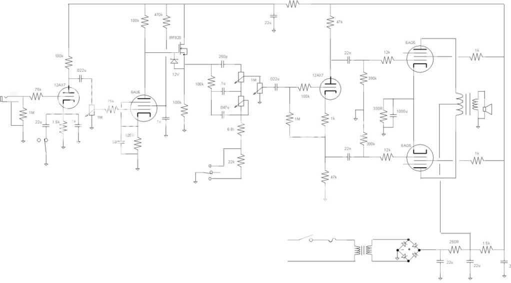
I just took another look at your circuit diagram to confirm that I had seen a semiconductor in the signal path, and
it suddenly struck me that something must have been left out of your drawing. You've got the FET connected directly to B+, and thus the tone stack is connected directly to B+ through it. Where does the signal go and how does it get there?
It also appears that the triode first stage and pentode second share B+ with no common filter capacitor at the top of their respective plate loads. Unless they are sharing part of their plate loads via what seems to me a voltage dropping resistor on the B+ line. Is that intended to be a form of negative feedback between them? But then, the FET suggests that you are trying to preserve every bit of gain from the pentode, except that there doesn't appear that there could be either pentode gain or FET signal feed-through if the drawing is accurate. If it is accurate (except for the missing cap between plate and cathode) then it would seem that you have "bootstrapped" most of any possible gain out of the circuit. Why?
What is missing from the drawing?
How does any signal get through?
Granted, there is no filter capacitor on the leg of the B+ supply your tone stack is connected to through the FET, but your first two stages feed from there also. What is the pentode doing to the signal if this circuit diagram is accurate?
And again, I suspect that the pentode circuit is not all correctly there, since it appears you've got the plate connected directly to the cathode. There's a capacitor in there, missing from the drawing, right?
What is the FET for?
Please don't take offense, but this circuit diagram baffles me completely.
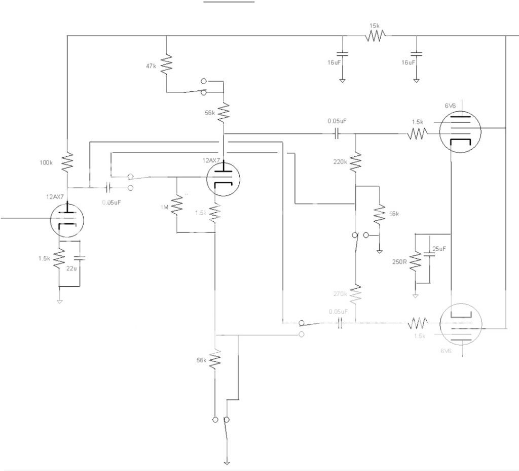
@Printer2:
I just took another look at your circuit diagram to confirm that I had seen a semiconductor in the signal path, and
it suddenly struck me that something must have been left out of your drawing. You've got the FET connected directly to B+, and thus the tone stack is connected directly to B+ through it. Where does the signal go and how does it get there?
Oops, cut and pasting from previous schematics where the parts line up differently. I will have to fix the schematic.
It also appears that the triode first stage and pentode second share B+ with no common filter capacitor at the top of their respective plate loads. Unless they are sharing part of their plate loads via what seems to me a voltage dropping resistor on the B+ line.
They share the same node, the 5.6k (subject to change) and the 22uF cap.
Not sure if I understand. I am on the learn as you go plan here and am just stringing stages together with the limited knowledge I have. I see I have made a mistake on my cut and paste again, I have the pentode plate and cathode tied together, I can not even imagine what the outcome would be other than a noise generator. Definitely have to fix.Is that intended to be a form of negative feedback between them? But then, the FET suggests that you are trying to preserve every bit of gain from the pentode, except that there doesn't appear that there could be either pentode gain or FET signal feed-through if the drawing is accurate. If it is accurate (except for the missing cap between plate and cathode) then it would seem that you have "bootstrapped" most of any possible gain out of the circuit. Why?
What is missing from the drawing?
How does any signal get through?
Granted, there is no filter capacitor on the leg of the B+ supply your tone stack is connected to through the FET, but your first two stages feed from there also. What is the pentode doing to the signal if this circuit diagram is accurate?
And again, I suspect that the pentode circuit is not all correctly there, since it appears you've got the plate connected directly to the cathode. There's a capacitor in there, missing from the drawing, right?
What is the FET for?
Please don't take offense, but this circuit diagram baffles me completely.
I can not even blame it being late in the night when I did it. Must have been on drugs. Will update right away.
Now that is odd, could not find the schematic as shown. Wonder if I copied the wrong page, I usually have multiple pages up when I steal from one to build another. I grabbed one closest to it had the cathode-plate mistake on it but the Mosfet follower-tone stack was fixed. Hope this next one is all right, it is what I intended.
Now I am not sure I would build it as shown now. I made the mistake of not having the cathode cap hooked up on the 6AU6. I had it without the mosfet (into my 6V6 amp) and it was fine but putting a tone stack behind it would load down the pentode. Now that I have tried it with the cathode cap and have excessive gain I could try it with the tone stack and no mosfet. It may just load down too much and need the mosfet, I will have to try it yet.
Today I am going to try going into the pentode first and then the triode. If it works out ok I may not do it with the triode first. The chassis was laid out for that arrangement originally, also if I can get as simple a circuit as possible, losing the mosfet, the better. Less to go wrong for the builder.
is that a semiconductor I see in the middle of your design carrying AUDIO? Please, not to be a prig or anything, but isn't this challenge an effort to build an all-TUBE amp? Or were the rules changed again while I was napping?
Back in post # 38 I asked this question:
Another annoying question. Anyone have a problem with using a mosfet follower in the signal chain like the PowerDrive circuits that I use in my HiFi amps? All active gain stages will be pure tube but a mosfet follower to drive the output tube grid can be used to eliminate blocking distortion. They are also useful to drive the tone stack. Just trying to maximize the bang for the buck equation.
The OP replied in post # 39:
By all means! If you can build a better mousetrap...
I haven't looked at the circuit in question since it will be updated, but there is a mosfet follower driving the tone stack in my 5 tube design. A mosfet just makes a better follower that a tube and actually affects the tone less than a tube does. I have been using them in my HiFi designs for about 7 years now. At first the "audiophile" world cried foul, but after people started listening to Tubelab SE's and building them, things changed and they have caught on with some more enlightened tube designers. The mosfet must be selected for low Crss and operated at a voltage where this capacitance remains constant to avoid PIM, but this isn't too hard to do.
Using a mosfet follower to drive the reverb tank caan save the cost of a transformer. I have also experimented with a mosfet PI in a guitar amp, and it works great but won't be unleashed here.
Please, I'm not picking at straws or trying to start any kind of debate with you, George, but the key idea in what I posted is that I can keep the plate current constant no matter what I use for a cathode resistor.
No need for debate, with 3 or 4 knobs to turn there are several ways to achieve the desired effect. I am also working off a slightly different formula. I squeeze as much clean gain as possible out of the pentode first stage then go through a simple tone and volume control into a starved triode for distortion. The volume and tone controls control the volume up to about half throttle, then control the distortion. The amp self limits at about 1.5 watts, maybe 2 under severe overload.
Using a mosfet follower to drive the reverb tank caan save the cost of a transformer. I have also experimented with a mosfet PI in a guitar amp, and it works great but won't be unleashed here.
I was going to use a mosfet to drive a reverb tank also, That poor amp has been sitting on the shelf since all this crazyness started. The mosfet for PI I would like to try on a real simple build, think it was design #5. Can't wait to see what you have up your sleeve. I wish I started on this amp building thing sooner, Just to think of all the trays of tubes I threw out when first starting work at the college. I did keep a handful, if I didn't I would not be playing with them now.
Can't wait to see what you have up your sleeve.
Sleeve, what sleeve.
.... I am away from home now and I was stuck at work for long hours before I left. I will be starting toward home tomorrow morning. I am sure long work hours will await when I get back since I have been gone nearly 3 weeks. I might have time to finish one of the two amps I posted before the long hours stuff started. The 4 tube amp is a pentode feeding a triode feeding a self split push pull pair. The self split limits the output and the gain a bit but it works good, sounds nice and doesn't get nasty sounding when pushed into heavy overload. I was experimenting with a mosfet PI instead of the self split just to see if it was worth the extra buck. If so I will add it to the PCB with the option to go either way. That design is decidedly low $$$ with the total parts list under $45. I don't remember the exact number right now.
The 5 tube amp is an exercise in using up all of the $100 budget to create a full on screamer. It makes 15 to 20 watts at full crank and has 4 gain stages for a full metal racket. An L-pad on the output can allow the racket at any power leven from zero to 20 watts.
Both amps use series string heaters to eliminate the heater transformer and allow for a $20 power transformer that can power 35 watts worth of amp. It idles at 20 watts.
I will continue to create guitar amps after the deadline, but they will not be constrained by budget or rules. I never quite finished my microprocessor controlled "dial a sound" amp that I started 15 years ago. It's time.
Just gave my two cents on another forum where someone wanted a Deluxe 5D3 rather than a 5E3, paraphase rather than cathodyne. I mixed and matched some of the values as they are different between amps but with the addition of a switch, one resistor, and the substitution of one resistor you get to have both PI's. It took an hour longer than I thought it should to do it, should be out cleaning up more leaves. Just thought someone here might find it interesting.
Hey, why is this picture large as compared to the others? Something to think about.
Hey, why is this picture large as compared to the others? Something to think about.
With all due respect, this does not work for me. The stipulation was for an "all tube" amp. That means tubes in the signal chain, wherever that may be, and nothing else. Semiconductors introduce thermal noise. There's no way around that."Another annoying question. Anyone have a problem with using a mosfet follower in the signal chain like the PowerDrive circuits that I use in my HiFi amps? All active gain stages will be pure tube but a mosfet follower to drive the output tube grid can be used to eliminate blocking distortion. They are also useful to drive the tone stack. Just trying to maximize the bang for the buck equation."
I'm using a pentode to drive the reverb tank AND the tone stack. The question is "how much current does the pentode draw." It's no big deal to get a pentode to drive a tone stack with a standard common cathode circuit. You just need a lower impedance plate load and a tube that draws a healthy amount of current, like the one I'm using. I've got a 7200 ohm plate load. That's all. The 4800-ohm original design didn't give me enough gain for the clean channel, so I rewired it. Still driving a reverb tank with no tranny, and a tone stack downstream. And I'm biasing it to 15 mA when specs for the tube call for 25 mA, so it isn't all that hard as some seem to think it is. By contrast, my front end triode draws less than 2 mA.
And the specs were for a 2 to 5 watt amp. Who needs to worry about blocking distortion or PI circuits in a SE design? Why would anyone need PP for a 5-watt amp? My 3.5W SE amp is TOO LOUD to play at 3 a.m. above half volume. Above 1/3 volume!
But "tube sound" means that the TUBES are CONTRIBUTING to the sound of the amp. This is why guitarists love tubes. This isn't a hi-fi amp. A clean clean is abhorrent to anyone who loves the sound of an electric guitar. Even my Martin acoustic likes SOME second harmonic in the sound."A mosfet just makes a better follower that a tube and actually affects the tone less than a tube does. "
Perhaps I'm among the few die-hard guitar-lovers here. I tend to doubt that, and I see George holding one in his avatar, but I'm a primitive cave-man old school guitar player who has a visceral aversion to semiconductors in a tube amp for a variety of reasons, number one of which is the word "tone". Semiconductors add an element to the signal chain that I would define as a "complete absence of forgiveness," which is my paraphrase for "affects the tone less." Maybe you are OK with that. I am not. Never will be. Not since my First tube amp was stolen and I bought an Electric guitar with a transistor preamp that sucked all the guitar out of the guitar and for the longest time I just couldn't figure out what had happened to the sound and why it was so unlike a guitar--being so clean and uninspiring. Gradually it dawned on me that clean is for hi-fi and guitar is not hi-fi. A "clean" guitar is a dead guitar. If sits in your arms like a block of concrete and doesn't respond to any loving.
This was one of my big complaints at the start of this thread. That after a certain amp was ravaged and belittled savagely to set this whole thing in motion, almost every sneer sent in its direction became inverted when the specs for this challenge were reconsidered and the "advantages" of making allowances for the very same complaints were adopted as part of the specs for the amp that was to be "an improvement" over the lowly thing that wasn't worthy of some.
Now some are building something that isn't worthy of that little amp that started this whole thing.
If "bang for the buck" is the only criterion, then by all means just build an all-transistor amp like the mass-market people (so long as you don't mind losing the target audience--the tube amp purist).
It isn't easy to get a good-sounding, real, ALL-TUBE amp at a low price. That was the whole point of this thing, or so I thought. If it isn't, then I'm clearly in the wrong neighborhood.
So now we have no need for power cord, no need for chassis, no need for speaker, no need for cabinet, no need for including shipping in the cost of parts, and no need of TUBES in the design where it's cheaper to use a thermal noise generator. And all of the complaints originally lodged against a certain "mere handful of parts" are now listed as specs for the new design criteria.
Please excuse me for a moment while I go into the next room to laugh for a few minutes.
Semiconductors introduce thermal noise.
Everything in the universe does. Including tubes. The idea that you avoid this by eliminating semiconductors is incorrect.
The concept of "the signal chain" is a fuzzy one. Would you consider power supply rectifiers to be in the "signal chain"? Bias diodes? Current source loads?
- Home
- Live Sound
- Instruments and Amps
- The Hundred-Buck Amp Challenge