Is this the big move? Or is that still a ways off in the future?
Not yet, just starting to relocate some furniture and "stuff" that I want to keep but don't use right now. I go up there at least 3 times a year, So we bought a small trailer and decided to start moving stuff slowly.
The date of the big move is still unknown. I still get a nice paycheck here and I am not going to do anything to change that. Unfortunately in this economic environment the actual "retirement" date will not be by my choosing, and is unknown to me. I'm hoping for "a ways off in the future."
Been awake all night so I am feeling a little stupid. The good news is that since I was up at 3:00AM last night I decided to do something useful that would not take too much effort. I went online and came up with a bill of materials for the amp.
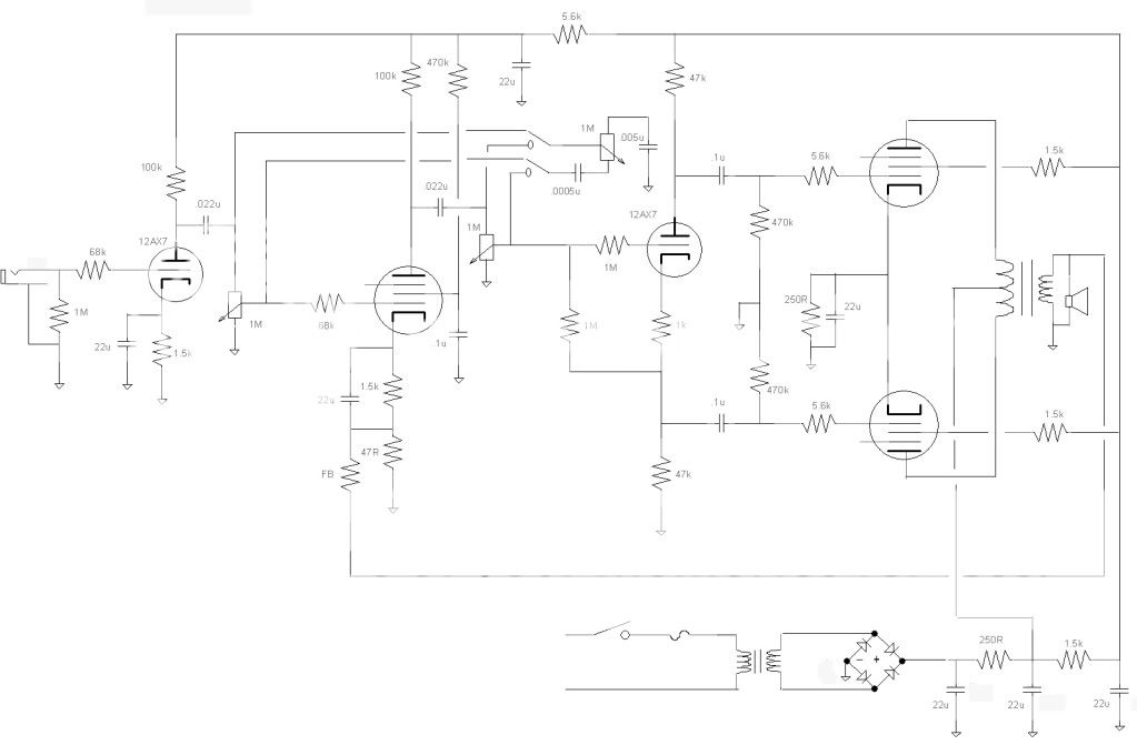
I stripped the circuit of anything not necessary in order to shave pennies. I was a little concerned that I would not have enough gain to crank the puppy, it could get to full output but not with too much to spare. When I found I had a fair bit of cash left over I splurged and went for a 12AX7. Rethought the operation of the circuit (probably not a good thing with a lack of sleep) and came up with a few more iterations. The latest one, Hundred Buck Amp 9, is a little more complicated than I wanted for a basic build but I am curious how it would sound. So I am giving it a try.
Of course the chassis I wanted to use is not laid out properly for the configuration so I am starting from square one again. I have been eying a cabinet that I wanted to build an amp into, because of the peculiarities of it the layout is not one I would advise anyone else using (still not sure how it will go together yet). If the circuit turns out half decent I will lay out something a little more builder friendly.
At least that is the plan today, tomorrow I may wonder what the heck I was thinking.
Well a couple of mistakes in the above, think I have it worked out though. Will go back to using the existing chassis I have, an important part of the other is missing (it is around here somewhere just running out of time) and it would not be right building it without it. So far $99.76 spent, any changes and I may have to start shaving corners again.
Prayers for a completely successful surgery.
I don't pray but I wish George the best - he's a great guy.
OK, this has nothing to do with this challenge but this demo sounds OK (not great). Tele Classic '72 Thinline + POD XT ( Fender Champ 1x8 Jensen speaker setting). Slight reverb effect. Second guitar (1:07) with tremolo + delay. It sounds much better than my previous one using mic + 100$ amp + soundcard. I will probably try again with my amp if I have the time. Something was seriously wrong with my first recording.
zSHARE - Jeff Buckley - So Real _demo-cover_.mp3
Not yet, just starting to relocate some furniture and "stuff" that I want to keep but don't use right now. I go up there at least 3 times a year, So we bought a small trailer and decided to start moving stuff slowly.
The date of the big move is still unknown. I still get a nice paycheck here and I am not going to do anything to change that. Unfortunately in this economic environment the actual "retirement" date will not be by my choosing, and is unknown to me. I'm hoping for "a ways off in the future."
All the best to you George, hope you're feeling better very soon!
Thanks for the words of encouragement. I have had issues with localized skin cancer for about 15 years. I will likely have them for the rest of my life due to excessive exposure when I was younger. Small cancers are zapped off with the "fire stick", an electrosurgery unit.
This is the third time I have had this type of surgery. The first time (over 10 years ago) went well and the cancer never returned. The last time (3 years ago) the cancer returned within a month, with a vengence. I finally convinced the surgeon that I had obviously missed my chance to be a TV star or a model, and I would rather be ugly and alive than pretty and dead. He finally got agressive and cut a grand canyon across my face. Cancer gone!
This time I went to see the same guy and convinced him that I wanted the lump gone. I got a big hole in my shoulder. The So far there have been very few complications other than some numbness in my arm. I saw the chunks taken out of my shoulder and I am convinced that this one won't be back. The doctor said that I was OK to drive, so I will be heading north as soon as I finish a power amp design at work. Likely Friday or Saturday.
I don't plan on returning until Oct 14 of 15, so it doesn't look like I will have anything more to contribute to this challenge before the deadline. As I said before I am not "in it to win it" so I will continue to post my endeavors in this thread as they happen. There are cabinets being made for the two amps that are already working, three speaker cabinets nearly finished, and another amp half built. There are also two more designs that were not made to fit the rules of the contest (too much power for too much money). All will be completed as time permits.
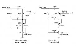
Does anyone know why the Blues Jr. tone circuit connects the midrange tone pot wiper only to the .022 cap whereas the old Fender circuit connects it both to the connection between the bass pot and the midrange pot and the cap?
I see that the Blues Jr. version prevents the bass wiper from being at ground when the mid wiper is at ground, whereas in the old Fender circuit, with bass and mid at ground, there is zero ohms to ground from the bottom of the treble pot. In other words, in the older circuit, with all tone pots at minimum, there is zero signal to the volume pot, whereas in the Blues Jr. there would always be at least 25k between the middle capacitor and ground. And because of the bass cap difference, the minimum configuration puts only .022uF at least 25k above ground (instead of the .1uF it would be with the cap in the older circuit).
Does the Blues Jr. not need as much bass boost/cut as the bigger amp? Because . . .
The Blues Jr. also uses a .022 for the middle cap (whereas the old
Fender circuit uses a .1 uF), and the midrange pot is 25k (instead of 10k as in the older circuit). I halfway understand that more than doubling the size of the bottom pot makes the Blues Jr. circuit somewhat equivalent to the other such that the two .022 caps add to .044 which is almost half of .1 and makes the RC product (in some settings) about the same. Still, it looks odd. In the Blues Jr. both lower caps are .022. In the older circuit, the middle (bass) cap is .1 and the lower (mid) pot is .022. The older circuit makes sense to me. The Blues Jr. is a question mark. But I may want to attach the .022 cap only to the wiper of the 10k pot, changing only that feature of the Fender original circuit. That way, some mid always gets though as a baseline signal. But perhaps its better if all three bands can go to zero. Any thoughts on this out there?
Anyone have any thoughts about the difference between wiring the bottom pot as a potentiometer as opposed to a rheostat?
--Tubekit
Classic Fender Tone vs Blues Jr. Tone circuits
Here are the schematics for the two different tone circuits.
Can anyone comment on the relative advantages or disadvantages of one circuit versus the other?
What would you expect to be the sonic difference?
--Tubekit
Here are the schematics for the two different tone circuits.
Can anyone comment on the relative advantages or disadvantages of one circuit versus the other?
What would you expect to be the sonic difference?
--Tubekit
Attachments
Is this the schematic that you're talking about:
http://support.fender.com/schematics/guitar_amplifiers/Blues_Junior_schematic.pdf
The middle control is a shelving circuit, as long as the pot is not set to zero ohms, the cap (C13) and mid control resistance determine the center frequency of the shelf. The mid control R also sets the height of the shelf. C13 is a shunt to ground through the pot. This shelf contour is very much like baffle step compensation but also probably provides some shaping for the speakers midrange response. It makes sense to choose the cap value based on the cabinet size and the speakers response curve. The mid circuit becomes a first order low pass when the pot is set to zero ohms, then of course the treble circuit with a low 250 pF cap allows some HF to pass.
The bass control is a first order high pass circuit where C11 is like an interstage coupling cap with the bass control resistance providing a variable cutoff freq.
The above assumes no interaction of the circuits and I've used simulations to get a better idea of what is going on.
I don't think it makes sense for the output to go to zero when the pots are set all the way down since they are intended to provide some shaping, not 100% attenuation.
This is a crude circuit and many are familiar with it as a result of the widespread use over so many years, but it seems to provide a significant improvement in the sound.
Here are the schematics for the two different tone circuits.
Can anyone comment on the relative advantages or disadvantages of one circuit versus the other?
What would you expect to be the sonic difference?
--Tubekit
The smaller bass cap helps to avoid speaker excursion overload with smaller, fewer, or less capable speakers. The original .1 uF was sized a bit large anyway.
The Blues Jr. mod fixes the issue of zero output with the pots all the way down. The behavior of the circuit is a bit odd with the bass pot all the way down, especially as the mid pot goes all the way up - again it is a crude circuit.
With the mid toward the bottom of the pot it acts as a shelving circuit in combination with the 100K R, but toward the top with the bass down the two caps are in parallel lowering the cutoff freq of the bass HP.
Last edited:
Wow, beautiful! That was the kind of answer that I was looking for.
Yes, I thought that this was a mod that specifically addressed the single, smaller speaker in the Jr. It's just that with the two lower caps at the same value, the visual impression is that the bass control has been gutted, not simply "tamed".
"[midrange] toward the top with the bass down the two caps are in parallel lowering the cutoff freq of the bass HP."
That's the part of it that I understood. And with the increase in the Midrange pot from 10K to 25K that compensates almost equally for the decrease from a .1 uF bass cap to the combined .044 of the two caps.
Yes, odd with the bass down and mid up is what I expected, and want to avoid, since many people like a boosted mid which then effectively requires some cut in the bass and treble.
Hmm. I think I'm going to try the circuit with the original cap values and control excess excursion by not turning the bass all the way up. I'll stay with the 10K midrange pot, but connect it as in the Jr. circuit.
Or maybe I'll go to a .047 for the bass cap.
Somewhere in here I sense the possibility of a compromise between the two extremes of crudity.
Thank you for that very informed and helpful reply.
--tubekit
Since it has been quiet.
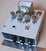
Not the best thing that I done but it is getting there. Bit of work to do on the other side of the circuit board and then start wiring up to the tubes. I have jumper wires in place for the plate, cathode, and screen resistors for the preamp pentode, still have to play with the values and it beats swapping parts on the board. The couple of parts that are standing off the board are also temporary till I pick up the right ones.
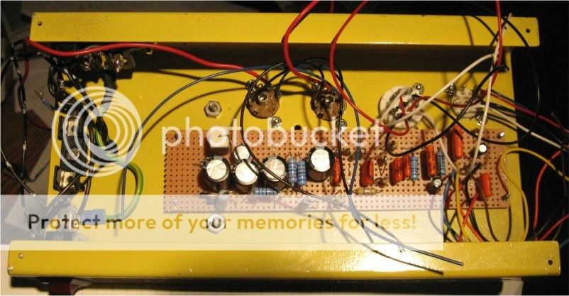
Not the best thing that I done but it is getting there. Bit of work to do on the other side of the circuit board and then start wiring up to the tubes. I have jumper wires in place for the plate, cathode, and screen resistors for the preamp pentode, still have to play with the values and it beats swapping parts on the board. The couple of parts that are standing off the board are also temporary till I pick up the right ones.
")
I think i have found someone to judge the amp challange, what do you think?
7 year old guitarist Zoe plays Sweet Child O Mine by Gun' 'N Roses - YouTube
Regards
Rob
7 year old guitarist Zoe plays Sweet Child O Mine by Gun' 'N Roses - YouTube
Regards
Rob
Thought I should check in for a few minutes and bring you folks up to date.
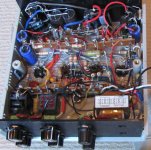
My entry in this contest was not going to be anything innovative. Due to my limited electronics background, I concentrated on building a solid, affordable variant of an established design. My circuit is simple; looking very much like a Fender 5C1 Champ or a Gibson GA-5 Les Paul Junior. Basically a 300-0-300 @ 75 mA power transformer, 5Y3, a lightweight LCRCRC filter section, and a 6SJ7 driving a 6V6 (or a 6EY6 in my case), into a 5K:4 ohm OPT.
Initial breadboarding was quick and easy, but then came the tweaking. All my iron was ordered new from Edcor, and this presented an unusual problem -- the inductors were simply too good. The XPWR014-120 power transformer, although rated at only 75 mA, is nearly twice the size of the vintage 70 mA Hammond and Thordarson transformers I have. The power supply simply will not sag. Similarly, the GSXE10-4-5K output transformers are huge compared to the original Fender and Gibson transformers. The output transformers refuse to overload and break up at maximum volume. Driving a Peavey Blue Marvel 8" speaker, the sound remains far too clean.
So I reached the point where I had a nice little four-watt monaural hi-fi, but a pretty unsuitable guitar amp (unless one was using it for acoustic folk or classical guitar, perhaps). I was about to tear down the breadboard and replace the inductors with something less robust -- and then everything got put on hold.
My 91-year-old father was hospitalized about a month ago, and has since progressed through a litany of procedures for a cascading series of problems.
Considering his age and frail condition, the prognosis is not good. I doubt he'll still be with us come Christmas, and could be gone much sooner. No one can predict when the next medical crisis will present itself.
Obviously, all fun-and-games have been put on hold -- the temporal and emotional demands are too great. I'll still pop in on this thread on occasion, but currently can't give any time to this project. I'll leave it up to the participants in this build-off to determine how you proceed.
Originally, the deadline was to have been October 30th, with a poll being posted to determine whose design won the paltry $100 prize. I'll still honor my commitment to award the prize money, but if you people want to extend the deadline, or modify the rules in any other way, please feel free to do so.
Carry on.
Obviously, all fun-and-games have been put on hold -- the temporal and emotional demands are too great.
I know how this goes. My mother and my mother in law both passed this year. Both were ill for a long time before passing too. I am currently at my mother in laws house 1200 miles from my amps helping my wife deal with the probate mess. Good luck with all that is to come.
I should be back for 2 weeks before the 30th. If that is the deadline, then I may have one amp working.
In the traditional guitar amp design the cheapness of all the components together tend to accentuate the distortion profile. This is especially true of old Fender designs. The tiny OPT tends to saturate when driven hard. This causes the output tube current to skyrocket dragging down the power supply causing the sag effect. Pop in big transformers and the effect diminishes.
Stuff a 6L6 into a Champ and it sounds cool until the power transformer fries. I was about 12 years old when I found this out. One of my friends also verified the "don't play bass through a Bandmaster" urban legend.
Oh the 30th, I thought the 15th. Well I feel better about not doing anything on the amp tonight, did not help I had to overlook a forum tonight I help mod. But given that amount of time I probably will change my mind again on the design for the 11th time.
Thankfully no health woes on my horizon, hope you all get through your challenges alright. I am not so much into the challenge other than the fact I find it interesting the directions and choices you take. I am concerned when the dust settles that this thread will also. Maybe we could do a mods/revisions on the designs or latecomers welcome thing to keep it going. Maybe a $150 amp? I am sure dumping the little OP transformer I am using for a real one would do wonders, but I think I am getting ahead of myself. Got to get Mark I up and running first.
Thankfully no health woes on my horizon, hope you all get through your challenges alright. I am not so much into the challenge other than the fact I find it interesting the directions and choices you take. I am concerned when the dust settles that this thread will also. Maybe we could do a mods/revisions on the designs or latecomers welcome thing to keep it going. Maybe a $150 amp? I am sure dumping the little OP transformer I am using for a real one would do wonders, but I think I am getting ahead of myself. Got to get Mark I up and running first.
- Home
- Live Sound
- Instruments and Amps
- The Hundred-Buck Amp Challenge