I am thinking of skipping that nice pretty chassis I posted a picture of in exchange for a beat up old box. I am just having a problem with the physical mounting of the components. The board is built reversed from what the cabinet needs and mounting the pots and tubes may also be an issue. That is if I ever want to service the thing. All because I want a sealed cabinet for the speaker. Hope I can figure it out, now why do I not just take the easy route?
I will continue to create guitar amps after the deadline, but they will not be constrained by budget or rules. I never quite finished my microprocessor controlled "dial a sound" amp that I started 15 years ago. It's time
I'm bodging together a little project using a pre based on the AX84 extreme project with, (sorry Tubekit!), a chip amp power stage. Plan is to convert it once you folks come up with the killer design
That microprocessor controlled amp that I made about 15 years ago......Didn't have a single tube in it. I made it completely from IC chips, mostly free samples from the National Semiconductor FAE. The remains of it are still around here somewhere but I stole its power transformer and heat sinks long ago. The SPI controlled equalizer chip and some of the others have gone extinct a few years back.
That amp was cool in the fact that you could spin the knobs on the front panel until you got the sound you wanted and then store it into a memory and then instantly recall it by touching a pad on the guitar. I like that especially in a live situation.
The amp was all solid state, and did have some redeeming qualities (mostly it was loud with two 75 watt chip amps), but it had no soul. It was expressionless, harder playing just made louder sound, the tone did not change unless you hit clipping which sounded pretty nasty.
I plan to keep the microprocessor control, but replace the signal path with a tube lineup.
The preferred method of controlling gain in a tube amp is an LDR (as used by Soldano and others) which IS a semiconductor.
As I said, it is an interstitial solution.
Just about to have some lunch, then I'll test the TPA1517 power stage, and post some pics and a schematic.
What is the heater current on a TPA1517?
What is the heater current on a TPA1517?
I looked it up. It is 22.5 mA per channel. All of that current is used to warm the chip when there is no signal applied.

Pics as promised.
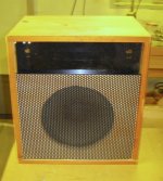
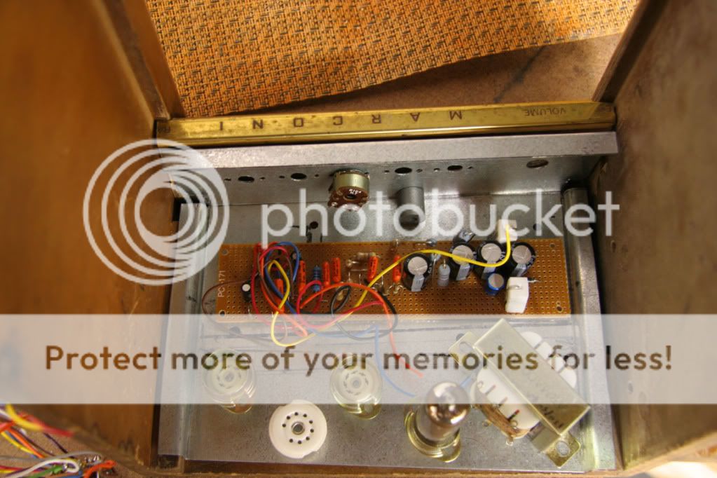
Firstly the cab, with a Celestion 8" speaker, no idea of the model as the label came off years ago, and then the old amp chassis with tone control. This chassis will be junked as it's too small to fit everything in.
I'll post pics of the new one once my camera batteries have recharged.
Attachments
It wasn't a "wire in a magnetic field" after all.
After running the hum problem down to the very last possibility (by, among other things, moving the tank return jack, then, when that didn't help, shorting the recovery stage grid directly to ground to eliminate all possibility that the hum was coming from the grid circuit, and finally, at wits end, even ruling out by simple arithmetic the far-fetched possibility that 25mA ripple on the plate of the triode in the same bottle was jumping the series 1.4 pF capacitance to the grid of the pentode,
it came down to that very one and only thing that one would never think to check nowadays before exhausting every other possibility by using almost every piece of test equipment in the lab, especially given that the device is a protype and the expectation cannot otherwise be than that any problem must be something that was inadvertently done by none other than oneself.
With the grid grounded and the plate and screen supplies at flat DC down to less than measureable at 5mV per division on the scope, the hum was still as loud as ever. It was completely baffling until the light came on. It had to be the tube.
It was the tube.
I replaced the tube and the hum went away. Spent a day and a half tracking that problem down, and it was the tube.
I must have somehow fried it during my "experiments," creating a new current path within the bulb. Not sure which lug of the tube socket the hum was coming from (Filament is DC), but it's gone now.
The really maddening thing is that after I verified that another tube was hum-free, I put the offending tube back in the circuit just to confirm that I was not simply hearing things, and less than a second after its hum started to become audible there was a "click" and the hum was gone.
I know I wasn't hearing things, though, because that loud hum is on all of the recordings I made yesterday.
I took the tube out and set it on a shelf. Every once in a while, I find myself looking at it to see if it's moved.
Still on thermal noise are we? Well, it's true that 5mV of thermal noise in a 100-volt p-p circuit is not going to be noticed. So I'll grant that the introduction of some here or there can be gotten away with, depending on where the here and there are. I mean, since you forced me to.
And yes, resistors generate thermal noise. But we can get rid of them. At least, we can get rid of the ones that are the worst offenders.
One bit of advice that is often given for restoring--or even improving--the function of a piece of vintage gear is to replace the carbon comp resistors with metal film resistors. Metal has a much lower thermal noise coefficient than carbon.
Because carbon is a semiconductor.
I replaced the tube and the hum went away. Spent a day and a half tracking that problem down, and it was the tube.
I have spent nearly a day chasing down some weird distortion which turned out to be the tube. The kicker is that I was using tubes borrowed from a working amp, AND they still work good in that amp. No specs (maximum grid circuit resistance can be responsible) were violated, but the amp wouldn't work with that tube.
I mean, since you forced me to.
I'm not forcing anybody, just stating my opinion, which seems to be different than yours. That's OK, and expected. You should have seen some of the hate mail I got when I first started putting mosfet followers in tube HiFi amps. A few even suggested changing my name to Transistorlab!
I will continue to go boldly forth where no tube circuit has gone before....If it doesn't work out, I will back up a bit and explore a different path. I am tired of building the same old stuff.
One bit of advice that is often given for restoring--or even improving--the function of a piece of vintage gear is to replace the carbon comp resistors with metal film resistors. Metal has a much lower thermal noise coefficient than carbon.
There are plenty of "audiophools" that would argue this point, but I agree here. I set out to measure resistor generated noise and distortion about 5 years ago but realized that my measurement floor was not good enough at the time. I may try again some day, but even then some NOS carbon comp resistors that I have had since the 1960's exhibited measurable distortion when exposed to the signal voltages commonly seen in a tube amp. I guess to some this is "good distortion".
I do not care what is in an amp as long as it sounds good. After messing around with this amp for a while I went and plugged in to a SS amp I built years ago using a 8" 70v PA speaker (no transformer). Clean it had the sweetest sound, you can hear how good a guitar it is. I need to put in a loop for some tubes to give it some distortion as it does not do that well.
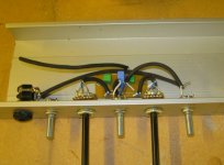
So I think I came up with an arrangement that will not cost me too much in volume from the speaker cabinet. It is already on the small side. It looks reasonable now but I know it is going to get ugly.
So I think I came up with an arrangement that will not cost me too much in volume from the speaker cabinet. It is already on the small side. It looks reasonable now but I know it is going to get ugly.
A few even suggested changing my name to Transistorlab!
I wouldn't go that far but since you're not pure anymore how about Hybridlab?
I'm useless with transistors, I only have built a kit (F5) and was always in fear of smoking the mosfets. I have the parts for a Salas shunt regulator and am always delaying that project. Calculating the required heatsinks puts me to sleep.
but even then some NOS carbon comp resistors that I have had since the 1960's exhibited measurable distortion when exposed to the signal voltages commonly seen in a tube amp. I guess to some this is "good distortion".
Sometimes they work and sometimes they don't. To steer clear of trouble it's best not to use them. I do because I love their shape and colors and don't mind a little fuzziness here and there.
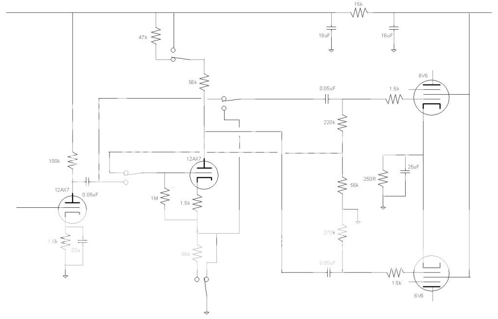
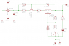
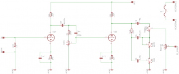
As promised, here's my working schematics - adjustable Maida reg so i can tweak the HV for the final design, and the worrking schematic for the preamp. I know this is a little off topic, but I'm posting this to encourage you folks to rescue me from chip amp oblivion.
Attachments
but I'm posting this to encourage you folks to rescue me from chip amp oblivion.
I see one possible problem. The input impedance of the TPA1517 is 60K ohms. The tone stack expects something much higher. It will work but some value tweaking might be needed. The tone stack calculator will tell you if it needs tweaking, or you could put a cathode follower or mosfet follower after the tone stack.
TSC
I wouldn't go that far but since you're not pure anymore how about Hybridlab?
There are two work benches in my lab. One is for Tubelab, the other is for silicon based life forms. Sometimes the little critters sneak off the SS work bench and try to hide behind a vacuum tube......
I am known for making more than a few tubes glow, and I blow one or two up every once in a while. I can say with certainty that I have fried far more Silicon and Germanium devices in my career than vacuum tubes. In fact I can add GaAs and GaN to the list too. Haven't fried any SiC yet, they are just too expensive to play with now.
I see one possible problem. The input impedance of the TPA1517 is 60K ohms. The tone stack expects something much higher. It will work but some value tweaking might be needed. The tone stack calculator will tell you if it needs tweaking, or you could put a cathode follower or mosfet follower after the tone stack.
Yup, I was pondering that myself. I'd like to keep the stack as is, so it's ready for a valve output stage, so I think a mosfet follower may be the way to go. A valve would be nice, but I only have one ECC83 in stock at the moment.
I have managed to complete the amp sections but havn't started on the Tremelo or Reverb sections yet.
I decided to test and debug the straight amp before continuing.
I ended up spending two days chasing a bad coax to the PPIMV which was causing excessive hum.
The amp is now moderately quiet unless you dial both gain and master volume beyond 8 out of 10.
The pentode stage has a bit more hum and noise than I like, but it is what it is. Most of the 6GH8s I have are used. A couple are new and are quieter than the used ones. I might try the noisy ones in the tremelo when I build it. Reverb will require a quiet one.
What's your tolerance for filter cap voltages?
QUESTION:
I already have my own opinion on this, but I would like to see how it compares with that of others. In order that I not influence the responses, I'll wait till later to post my own response to it.
How much over the rated voltage of an aluminum electrolytic capacitor are you willing to go in a circuit?
In case this sounds like a bad question to begin with, let me rephrase it.
Suppose you had built a prototype in which you used a 250-volt filter capacitor because you expected about 240 volts across it and you measured 252 volts across it when you got everything put together. Would you replace the cap with a 300 volt unit, or would you say "close enough"?
And if you would say, "close enough," at what voltage would you draw the line and go for the higher rated device?
Or if you would NOT say "close enough" at what voltage would you draw the line on a 250--volt cap. At 249.99? Or at something lower?
Huh? Wha? Off which topic?
Is that a 500K Gain pot?
That's what I'm using.
As promised, here's my working schematics - adjustable Maida reg so i can tweak the HV for the final design, and the worrking schematic for the preamp. I know this is a little off topic, but I'm posting this to encourage you folks to rescue me from chip amp oblivion.
Is that a 500K Gain pot?
That's what I'm using.
.
How much over the rated voltage of an aluminum electrolytic capacitor are you willing to go in a circuit?..
In the past I'd have said to always allows at least a 20% margin. I'm conservative that way. But then I just complete a Fender Champ clone and the 450V caps are getting pushed past 450V to about 460 during power up. The b+ voltage comes up about 10 seconds before the power tube conducts the pulls B+ lower, below 400V. If I build another one I'll go with 500V caps but I'm not changing what's in there. They seem to be working just fine. If ever they fail I'll put in 500V caps
Is that a 500K Gain pot?
1 Meg, simply because that's what I had in the bits box. I'm trying to build this without actually buying anything, we'll see how foolish that turns out.
Got the gas man coming round today, once he's gone I should be able to crack on with this.
- Home
- Live Sound
- Instruments and Amps
- The Hundred-Buck Amp Challenge