There's a low cost chassis, they could be screwed together:
The Squirrel Monkey One Tube Guitar Amp
I like the cheap chassis concept, but I have and will again here, warn people that the method used to generate B+ in this amp is POTENTIALLY DEADLY. Unfortunately someone without understanding of transformer construction propagated this idea onto the internet and it has been circlulating for a few years now.
A proper power transformer should have AT LEAST two barriers between the line voltage and the user. A medical grade transformer will have 3 or 4 depending on use and power level.
The usual two barriers are the wire insulation, and a layer of paper, mylar, or tape. Most bobbin based transformers have seperate compartments for the primariy or primaries, and the secondaries. This makes accidental shorting almost impossible.
The transformer specified in the squirrel monkey amp is indeed a dual compartment transformer, however its connection purposefuly violates this protection by using one half of the primary as a secondary. Moreover since only half of the intended primary is being excited it will overheat since the wire is receiving up to twice the current that it was intended to carry. The two primary windings are usually wound concurrently, so the only thing that prevents connecting your circuit AND THEREFORE YOUR GUITAR into the wall outlet is a thin layer of insulation on a wire that is overloaded.
Yes the designer specifies a grounded line cord, but that can not be guaranteed to save your butt especially if the amp gets used in a live gig where the house wiring is unknown, and the guitar player may be hot, sweaty, and drenched in beer. Guitar players have been KILLED live on stage in exactly this manner. Please don't go there.
I agree that wiring did not look good to me at all, he should just get a transformer that is a better match to the application.
Here's another tip for cutting costs without compromising performance. A linear pot can easily be converted to an audio-taper pot by simply bridging its terminals with a 1% resistor. I use this trick all the time to save five bucks or more on volume controls.
Five Bucks? Yikes. I pay $1.75 for both linear and audio pots. AES has a full selection of the good "Alpha" brand 24mm pots at that price every day the have US size 3/8" threads. For $1..40 they have the same pot but with metric 8mm nuts. The amp I have right here has 7 pots, No way woul I have spent $5 each on those. OK, Actuall I paid a Little more last order for Pots. I try the ones Webber sels. Tey are the best I've found so far. Still the same brand Alpha, but these have 3/8" brass treads and a more precision feel but still well under $2 each
Same with resistors. I like to use either 1/2W or 1W metal film 1% resistors an never pay even 5 cents for them. You must be shopping at the wrong place to pay those prices
I think that is the trick to getting the cost down, findingsuppliers who have most of what you need at the best price with cheap shipping. Also, I tend to think three projects ahead. Shipping will kill you on small orders.
A proper power transformer should have AT LEAST two barriers between the line voltage and the user. A medical grade transformer will have 3 or 4 depending on use and power level.
The usual two barriers are the wire insulation, and a layer of paper, mylar, or tape. Most bobbin based transformers have seperate compartments for the primariy or primaries, and the secondaries. This makes accidental shorting almost impossible.
Funny you should mention that.
I have had a few PT's that went dead short on the primary.,
Very dangerous.
Good thing I use light fuses on the bench.
I disassembled one of these failed units , it is current production power transformer that was made for guitar amp use.
This is a standard production item.
Check out these photo's
This shot was after removing a couple layers of tape used to secure the leads.
No obvious issues,
An externally hosted image should be here but it was not working when we last tested it.
5V tap, I thought it odd that there was nothing between the lead that crosses everything to its termination point.
An externally hosted image should be here but it was not working when we last tested it.
6.3V tap
An externally hosted image should be here but it was not working when we last tested it.
HV Tap W/Bias Tap
An externally hosted image should be here but it was not working when we last tested it.
Man, that was a heck of a lot of wire!
An externally hosted image should be here but it was not working when we last tested it.
Internal Shielding over primary.
An externally hosted image should be here but it was not working when we last tested it.
Battery died before I got any primary pictures, but it was basically just like the filament taps, heavier wire, more of it, and unprotected wires crossing each other at the termination point.
Due to the proximity of the soldering, it is difficult to tell if it was heat related during final lead soldering, or damaged due to sloppy assembly.
One thing certain, had there been an insulation layer where these wires crossed it would have likely not failed.
An externally hosted image should be here but it was not working when we last tested it.
To bad I had to take everything else off to get in that deep, I could have saved it.
Funny you should mention that.
I have had a few PT's that went dead short on the primary.,
Very dangerous.
Good thing I use light fuses on the bench.
I disassembled one of these failed units , it is current production power transformer that was made for guitar amp use.
This is a standard production item....
What was the make and model of this transformer?
Nice looking amp, Cassiel.
Thanks. It looks OK, my woodworking skills are bellow par.
What kind of construction (flat sheet metal chassis, Bud Box, etc).
L- shaped aluminium sheet.
I like the cheap chassis concept, but I have and will again here, warn people that the method used to generate B+ in this amp is POTENTIALLY DEADLY. Unfortunately someone without understanding of transformer construction propagated this idea onto the internet and it has been circlulating for a few years now.
A proper power transformer should have AT LEAST two barriers between the line voltage and the user. A medical grade transformer will have 3 or 4 depending on use and power level.
The usual two barriers are the wire insulation, and a layer of paper, mylar, or tape. Most bobbin based transformers have seperate compartments for the primariy or primaries, and the secondaries. This makes accidental shorting almost impossible.
The transformer specified in the squirrel monkey amp is indeed a dual compartment transformer, however its connection purposefuly violates this protection by using one half of the primary as a secondary. Moreover since only half of the intended primary is being excited it will overheat since the wire is receiving up to twice the current that it was intended to carry. The two primary windings are usually wound concurrently, so the only thing that prevents connecting your circuit AND THEREFORE YOUR GUITAR into the wall outlet is a thin layer of insulation on a wire that is overloaded.
Yes the designer specifies a grounded line cord, but that can not be guaranteed to save your butt especially if the amp gets used in a live gig where the house wiring is unknown, and the guitar player may be hot, sweaty, and drenched in beer. Guitar players have been KILLED live on stage in exactly this manner. Please don't go there.
Thanks for speaking up about this. Actually, I think you're being too kind, as it has not only been propagated on the internet, but specifically on this forum. It helps to have a voice against this kind of practice.
What was the make and model of this transformer?
Honestly,
I would rather just use this as a cheap can sometimes be self defeating example rather than a manufacture bash so we will leave that part out.
For that ultra cheap aura, a "Sardine Can Chassis" for $0.45 (no affiliation ...)
METAL BOX W/ HINGED LID | AllElectronics.com
Apparently 4.25 x 2.25 x .75 inches (see customer comments), maybe could use two of them for chassis ends with a board across.
METAL BOX W/ HINGED LID | AllElectronics.com
Apparently 4.25 x 2.25 x .75 inches (see customer comments), maybe could use two of them for chassis ends with a board across.
Actually, I think you're being too kind, as it has not only been propagated on the internet, but specifically on this forum.
And I say the same thing every time I see it.
I've started playing with various input/gain stage topologies in TubeCad. It quickly occurred to me that I really didn't know what kind of signal I was trying to amplify. I'd seen a post that a typical electric guitar had a 400mV output, but I'd also seen references to multiple humbuckers putting out ten times that voltage. And what about impedance?
A quick internet search led me to a site where someone has already done all the work, documented the process really well, and tabulated their results in an Excel spreadsheet. Makes things MUCH easier when you're not groping blindly in the dark. Here's a link to the site: UIUC Physics 498POM Guitar Pickup Measurements
Hope this proves as useful for you as it was for me.
I've started playing with various input/gain stage topologies in TubeCad. It quickly occurred to me that I really didn't know what kind of signal I was trying to amplify.
The link contains lots of cool information, but says little about what the voltage level is at the end of the guitar cord is while the guitar is being played by a human. I made the 50 to 400 mV statement based on numbers I wrote in my logbook nearly 20 years ago. Back then I had ONE rather beat up Univox / Mosrite guitar. I still have it and a Epiphone Les Paul, and a $99 Mexican Squire Fender Stratocaster. Time for some new measurements.
For years the standard load across the input of a guitar amp was 47K or 68K. Lately I have seen values as high as 1 meg in published schematics. Obviously the load will affect the tone and level of the guitar.
Fedex has already dropped 100 tubes, 25 sockets, and 2 power transformers at my house. UPS should be delivering my AES order today as well. It has travelled over 5000 miles to get here. I have several commitments that I can't ditch this weekend, but some science should occur.
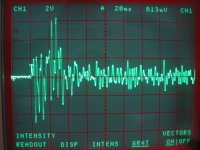
Guitar pickup output voltage
Here is a measurement.
First shot is the biggest signal I can make, which is over 6 volts peak crest. This is playing a fat 'G' bar chord on the 3rd fret with about as much bite as I can muster.
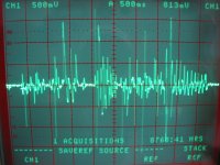
The next trace is 2 bars of riff from "Funk 49" (with the chord in the middle and the vibrato at the end...) played rather aggressively. This hits about 1.7 volts peak crest. Interestingly, the chord only peaks slightly higher than the hottest individual notes.
These are using the hot treble pickup on my Les Paul Studio into 10M impedance. The pickups are about 5K source impedance so the normal loads don't make much difference in the level. Switching in both pickups results in lower peak level.
I'm currently playing with a grid leak biased EF804 input stage which gives me some nice smooth crunch on my treble pickup as long as the input cap is not too big.
Michael
Here is a measurement.
First shot is the biggest signal I can make, which is over 6 volts peak crest. This is playing a fat 'G' bar chord on the 3rd fret with about as much bite as I can muster.
The next trace is 2 bars of riff from "Funk 49" (with the chord in the middle and the vibrato at the end...) played rather aggressively. This hits about 1.7 volts peak crest. Interestingly, the chord only peaks slightly higher than the hottest individual notes.
These are using the hot treble pickup on my Les Paul Studio into 10M impedance. The pickups are about 5K source impedance so the normal loads don't make much difference in the level. Switching in both pickups results in lower peak level.
I'm currently playing with a grid leak biased EF804 input stage which gives me some nice smooth crunch on my treble pickup as long as the input cap is not too big.
Michael
Attachments
Here is a measurement....
This confirms what I've read for years, that guitars are mostly at about 1 volt but can go to 2V and much higher in some cases. I think the 6V spike on the "G" chord is because for one or two cycles the waves all added constructively. All three "G"s plus harmonics of the other notes must have been in phase at two points in time. The dynamic range is huge. I think this is why live music sounds different. Anyone, and you don't need to have "golden" ears, can hear in a minute the difference between a live electric guitar and a recording. And it's not just the volume level. If I play a few notes on a low powered amp that is turned way down it still is easy to know it is a live guitar sound.
The osciloscope photos also show why the sugestion to record some ruff and shared then so we can hear the sound of the amp with the same input will not work. First how many of us have playback equipment that to make a 6 volt peak output. and if so does you playback equipment of the same source impedance as a guitar?
The other more serious problem (the first one can be addressed by building a small preamp) is that a player will adjust effort on the pick based on the sound of the amp and play it at the point he likes. This will be "wrong" for most amps other than the one he i listening to.
We see the same thing in MIDI recordings of piano music. The pianist might play just hard enough on the keys to make the timbre have a certain brightness in it. But if you play that same MIDI file back on a different piano it will sound not as good. But the pianist would have played differently on the different piano.
The fact is that with both guitars and pianos the timbre changes as you play it harder and the player does this by ear and it is a very non-linear process. Recording made on one instrument don't transfer to another
Last edited:
I'm a bit surprised to see that high an output but what ChirsA says makes sense. I looked at the output of a cheap (Grizzly) and at mid settings I was getting around a volt peak with my meager attempt at chords.
I noticed that walking down Duval st in Key West. As I walked past bar after bar, I could tell from at least a block away whether was live or recorded.
I noticed that walking down Duval st in Key West. As I walked past bar after bar, I could tell from at least a block away whether was live or recorded.
I think it would be good to have a common wave file that is used to test the amps, record someone good direct from the pickup, and we could duplicate the DC resistance and inductance of the pickup on playback for those who want a more accurate situation. Assuming a low impedance source such as the output of a sound card OP amp a pickup of the same type could just be put in series to duplicate the source impedance.
As I walked past bar after bar, I could tell from at least a block away whether was live or recorded.
The obvious thing that tips me off is the dynamic range of live music VS the sqashed and strained stuff that flows from a modern CD, radio compresses it even further.
The 50 to 400 mV numbers that I quoted were RMS numbers made after the initial note attack. I used the best instrument that I had back then an old HP331A distortion analyzer that reads RMS on a perfect sine wave, and something close to RMS as the distortion goes up. I used an opamp buffer to provide a very high impedance. The 331A was calibrated with the buffer in place. I worked in a cal lab then.
When you pluck a guitar string you move the string a few MM off center than let it go. There will be a huge low frequency transient as the string flies by the pole piece on the pickup and then settles down into a decaying wave form. The transient is far larger on the neck pickup because the string displacement is larger. The bridge pickup has a smaller transient unless the strings are picked right over the pickup.
The signal from the neck pickup is nearly a sine wave after the initial whack, while the bridge pickup has many harmonics throughout the entire note. Of course the type of pickups, the adjustment of the pole pieces (if they are adjustable) and the spacing of the pickup to the strings affect things a lot.
The huge transient that the flying guitar string makes will blow speakers and saturate OPT's if you have excessive low frequency response. I learned this back in high school with a home made solid state guitar amp. I blew a lot of speakers before I figured out that guitar amps have smaller coupling caps than HiFi amps for a reason.
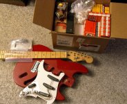
I unpacked 4 boxes of parts, and put them all in one box. There is $350 worth of parts and $60 worth of shipping in that box. I also put my guitar next to the box and took a picture. Obviously I have a bit of work to do even before I can measure the guitar. I took it apart over 2 years ago to make some measurements, because I am making a guitar too, but that is another project. I'm still ahead of the guys that don't have guitars.
Attachments
My son learned on a Squier pretty much exactly like that,
and since he stuck to it I went to look for a used American
Strat for him a few years later. I stopped in at a small
shop where our boys took lessons and the owner there
pointed me to a Mexican made Strat copy - not a Squier.
He said I have a 1960s American Strat and I almost like
this thing better. I didn't believe him, so I brought my
son out to play it and he liked it and wanted it so we got
it. It was relatively cheap, under $200. Paul practices at
a friends house where his friend there also has an American
Strat that has been in his family since the 1960s. He is
very serious about playing and has done some recording.
Paul leaves his guitar there, and his friend used Paul's
Black Strat copy to do a recording session over the American
Strat, LOL! I don't remember the brand at the moment.
Last edited:
Has anyone ever played with "Flathead" transformers as OPTs?
"Flat Head" ? Low Profile | Signal Transformer
I've got a little LP-10-600 that is rated at 6VA with dual primaries and dual 5V secondaries. Split bobbin construction with two bobbins. Each bobbin has a primary and a secondary.
They are rather inexpensive at about $12 ea.
I thought about trying to drive one primary and take the second one for B+ but it would only be good for around 18mA if the secondaries were unloaded. No chance of driving a filament with the secondaries and pulling any current from the spare primary.
So, I wonder if they would work as a cheap output transformer? with an 8 ohm load on the parallel secondaries the primaries would be around 8.5K p-p.
- Home
- Live Sound
- Instruments and Amps
- The Hundred-Buck Amp Challenge