kmj, sorry for the delay, too much work...
np.
I'll probably work something out, I only wanted to know if these values really are that critical sonce they have been changed a few times.
But thanks for all help guys
")
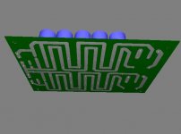
As I promised before I post my simple method to make my own low-ohmic resistors. The procedure is very simple - you just have to crack a wirewound resistor, take out the wire, calculate the resistivity per length relation and cut it down to the appropriate length.
Some more words and pictures on my website.
Mick
Some more words and pictures on my website.
Mick
doubling the voltage?
Having been so sonically impressed by Carlos' regulated LM338 design, I don't need another lowish voltage power supply. BTW I made it with 3x1500uF caps and so far, embarassingly small transformers... but I digress
But I have a P101 project brewing that looks like it could do well with a variation of this unregulated supply for higher voltage (+/-58V rails)
Other than adjusting R1 and R2 way up so they don't sizzle instantly, is there any other major alteration for higher voltage operation or does this change everything and all bets are off?
Re: doubling the voltage?
Hi Aghead,
R1 and R2 are the bleeder resistors and it's not very important the value you use, for that voltage you can use 4.7K instead of 2.2K.
You don't need to change anything else, you can use this PSU at those voltages you need.
Just use 80V or 100V electrolythics.
Aghead said:But I have a P101 project brewing that looks like it could do well with a variation of this unregulated supply for higher voltage (+/-58V rails)
Other than adjusting R1 and R2 way up so they don't sizzle instantly, is there any other major alteration for higher voltage operation or does this change everything and all bets are off?
Hi Aghead,
R1 and R2 are the bleeder resistors and it's not very important the value you use, for that voltage you can use 4.7K instead of 2.2K.
You don't need to change anything else, you can use this PSU at those voltages you need.
Just use 80V or 100V electrolythics.
Got an idea this afternoon :
why not use a big self (inductance/choke) instead of the 1R series resistors ? (R3 and R4 on the schematic)
It would be a self with the highest possible value, and wounded specially to get the same resistance as the series resistor.
The self would reject the HF rubbish naturally (it is a self), act like the resistance on DC current (because of the finite copper wire resistance), and act as one more power reservoir like a capacitor does.
I did some calculations :
a 23*14*7mm 3E25-grade tore, wounded with 0.6mm copper wire, allows 74 turns (probably more if you wind it several times arround the tore) has :
- 0,1R resistance
- 20mH inductance
Gotta try it on my LM4780 amp, I'll probably order the components this week (ferrite tore and enamelled copper wire).
Any suggestion/comment/idea ?
Vidalgo said:This choke will kill the sound from class AB amplifier.
Ah yeah ? Why ?
Maybe it would reduce the current inrush on transcients, and limit the dynamics ?


I finshed the p101 with this psu and have given it some listening time.
THought it was pretty good until going back to the bare bones 3875 with carlos' 338 regulated unit - the difference is quite awesome in detail and speed, but the 101 certainly has balls and is clean at high output.
But one mod I made was to use C9,10 as 2nf instead of 1.5 which I didn't have.
Still, the difference was much more open and accurate when adding the snubber and C7,8 compared to the big caps alone.
Carlos, is this C9,10 value critical?
Aghead said:Carlos, is this C9,10 value critical?
No, it's not critical.
You can use a value between 1.5~3.3nF.
thirst for knowledge
Greetings Carlos
OK I confess: understanding power supplies is my weakness. I have searched and it doesn't come easy to me. I have built several amps; all from kits, and power supplies were my stumbling block. It's a miracle I have any hair left. I am building my 1st point to point wired 3886tf amp, and i did get the power supply working.
Excuse my ignorance, could you help me understand a little better.
Please explain: power supply rails, why does the amp need 3 ? a positive, negative and a central rail to function?
Would a mono amp also need 3 connections?
Also measuring voltage from+ to - is double that of + to ov? and -to ov.
No doubt a lot of annoying questions but I would like to understand more about this principles and would appreciate any basic info.
It is hard to reveal that i don't know these things; but I have other strengths; such as building cases.
cheers
doggy
Man U got battered. Now's the time to ask anything you want of Carlos.Nuuk said:Doggy, depending on the result, you may, or may not get an answer after the Benfica v Man Utd game! (At present it looks like he may be in a good mood!)
- Status
- This old topic is closed. If you want to reopen this topic, contact a moderator using the "Report Post" button.
- Home
- Amplifiers
- Chip Amps
- The (high-cap.) unregulated PSU for chipamps