Nuuk said:Doggy, depending on the result, you may, or may not get an answer after the Benfica v Man Utd game! (At present it looks like he may be in a good mood!)")
Vikash said:
Man U got battered. Now's the time to ask anything you want of Carlos.
Nuuk said:Now he is probalbly too drunk to explain anything - better wait till tomorrow!
You...

We win!!!

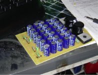
Again a few pics of my pcb i plan to make for my psu. based upon carlosfm schematic!
al those little caps are 1000uF/50V nichicon and the big ones are 4700/63V nichicon. bridges are GBPC3504W types.
anyone some comments? what could i improve? what did i do wrong/right?
Thanks in advance
al those little caps are 1000uF/50V nichicon and the big ones are 4700/63V nichicon. bridges are GBPC3504W types.
anyone some comments? what could i improve? what did i do wrong/right?
Thanks in advance
Attachments
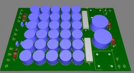
board size is by the way 12cm x 18cm not so small.. But i think i can't get it any smaller!
will this PSU with a 300Va 25-0-25 Tranny be sufficient to power 2 ESP P3A's ? an maybe 3 but then with a 500VA tranny?? ( but that's for the future.
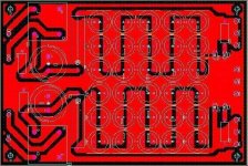
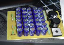
and the copper bottom pic:
will this PSU with a 300Va 25-0-25 Tranny be sufficient to power 2 ESP P3A's ? an maybe 3 but then with a 500VA tranny?? ( but that's for the future.
and the copper bottom pic:
Attachments
fixation said:will this PSU with a 300Va 25-0-25 Tranny be sufficient to power 2 ESP P3A's ? an maybe 3 but then with a 500VA tranny?? ( but that's for the future.
I think so, but I would use at least 20,000uF capacitance after the series resistors.
Unless you have already bought all those caps, consider using 1,500uF or 2,200uf (x15, as you have).
Check it out if you can make a smaller board by using 3,300uF or 4,700uF caps in parallel, for a total of around 30,000uF.
fixation said:and the copper bottom pic:
Much better.
Viva Benfica.
fixation said:and the copper bottom pic:
Just one remark, I don't like those traces between the bridges and the first caps. Avoid those corners (on the bleeder resistors), at least fill that up, allow a straight path from the bridges to the caps.
Attachments
carlosfm said:
Just one remark, I don't like those traces between the bridges and the first caps. Avoid those corners (on the bleeder resistors), at least fill that up, allow a straight path from the bridges to the caps.
It looks like FIXATION is using the same PCB program as I (Multisim) --
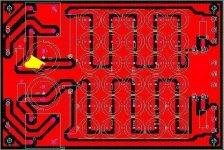
To get rid of that nasty vertex Carlos points out you can drag the power trace towards the ground plane and the vertex will melt away, you can fatten up the trace which will force the vertex to shring. You can also but a "prohibited" area -- in the form of a polygon. Make sure your mitering settings and trace separation are set properly.

fixation said:and here is the result......
I thinks it looks a quite nice....
It does.
Benfica is big.
http://www.hawkaudio.com/tips.htm / Silicon Rectifiers
I wondered, when we are already using series resistors in our PS (CRC...),
then why dont we put also one between the sec and the rectifier, against
the cooperation between the trafo's L with the diodes' C ?
(Or at least snubbers on the rectifier, to prevent a local resonance here)
But my other problem is: what can do a snubber with "asimmetrical" spikes (with DC component),
for example when a rectifier diode produces a 1V spike in every period but only a "+ halfwave".
A C can just filter DC = 0 "signals" and that also just when the values, and the timebase is
appropriate. Or maybe a snubber at a place like this wouldnt reduce this pike (the cause), but
just the resonance what it caused (the effect) ?
And the wiring: should we twist our wires to reduce the EMF radiation or this would just increase
the cables inductivity and therefore the resonances ? Or this is place-sensitive question ?
(like PS cables (AC, DC) vs. signal cables (low-level: interconnect, high-level: speaker-cables)
Waiting for your comments and of course for your experiences on this !
Probably people in this thread and carlos can help.
http://www.diyaudio.com/forums/showthread.php?s=&threadid=69652
LM3875 with snubberized PS on the same PCB ??? Post #1
Hi,
I plan building a power amp using LM3875 for my OPA3124 pre (ESP88). I wonder if
1). Can the LM3875 and big PS (10,000+1500FC+0.1 per rail) be in the same board? ( One tranny 24-0-24 240VA per channel)
2). Will it hurt from the current ripple can cause hum or ground problem?
3). Will having 1 Ohm res between the main ground and the signal ground help?
4) Will having 0.1 Ohm 5 W in series between the 10,000 cap and 1,500 cap help?
5). Is the (10,000+1,500FC) overkilled, or (4,700 + 1,500FC) per rail is sufficient?
Please advise.
If somebody wants to try things on the PS...
I read about this resistor trick around the rectifier on a lot of sites.
Many people use it, so nobody want to try it on a GC PS ?
I dont have my GC now, I gived it to my friend for a month...
We just have to put a little series resistor (0.47 - 1R) between
the sec and the rectifier and also between the rectifier and the caps.
Certainly we can also put one between the big caps too, like in Carlos' design.
And there are still things to try like little filmcaps on the diodes,
maybe snubbers, etc...
I did try this awhile back and could not discern any improvement.
Maybe it's subjectivism coming into play because I wasn't expecting any improvement.
The voltage peaks mentioned in hawkaudio's site are supposed to be damped by proper supply decoupling. Nobody uses just a big electrolytic - my Parasound amp for example, has big C, medium C, small C in parallel. If you increase the transformer impedance with that series resistor, you'll also slow down the charging of the main caps.
Like Carlosfm said, I'd simply build my gainclone PSU from a bank of electrolytics, properly decoupled. Nothing new here really, e.g. McCormack's DNA "technology".

I know these are basic questions but:
*Why not use a regulated power supply? Do gainclones like unregulated better?
* Does an e-core transformer provide better regualtion than air core torroid?
* Do gainclones sound better with battery power which is cleaner than AC from the wall?
Thanks
*Why not use a regulated power supply? Do gainclones like unregulated better?
* Does an e-core transformer provide better regualtion than air core torroid?
* Do gainclones sound better with battery power which is cleaner than AC from the wall?
Thanks
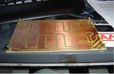
My latest LM3886 boards
Hope that will sound even better
Now is burning
An externally hosted image should be here but it was not working when we last tested it.
An externally hosted image should be here but it was not working when we last tested it.
Hope that will sound even better
Now is burning
- Status
- This old topic is closed. If you want to reopen this topic, contact a moderator using the "Report Post" button.
- Home
- Amplifiers
- Chip Amps
- The (high-cap.) unregulated PSU for chipamps