by Jkeny - I was just trying to tease the last drip of performance out of what seems a superb design
Well , I got it.. thanks for links.. tried different diodes,
even transistors and the opto- bias. The technics approach
seems to have the least effect regarding OLG, and the
other aspects of the amps performance.
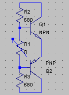
NEW CLASS A _THE FRUGAL WAY
An externally hosted image should be here but it was not working when we last tested it.
The choice of resistors is critical , the P and N Sides are a little different but that seems to be true in a normal EF type 2 as well.
Still..., it performs as advertised, P or N never completely turn off,
with even the possibility to adjust the class A idle current.
OS
jkeny said:Why not have a look at something unique - like Nelson's optobias here: http://www.diyaudio.com/forums/showthread.php?postid=1679112#post1679112
As the poster says seems simple & elegant!
That thread is talking about the patent below.
http://www.pat2pdf.org/patents/pat4752745.pdf
I use one of these circuit in my circuit, which I will hopefully be able to build:
http://www.diyaudio.com/forums/showthread.php?s=&postid=1727486#post1727486
The BJT bias (and probably the optobias as well?) will lower bias current as the BJTs get warm, this might be used to good effect for tempco.
Also, you could try this bias generator (attached) as it works far better than the one transistor version. Bias voltage will be much steadier. With R2 and R3 at their current values you will have about 1mA through the resistors as there will be about a .6 voltage drop across each.
- keantoken
Attachments
Congratulations OS for your so called non switching Frugal Amp design.
This shows how only 2diodes + resistors can do whatever you want to achieve in terms of non switching hype in virtually every popular O/P configuarations (T, EF, CFP etc).
Here are some measured benefits of typical non switching B class:
http://www-f9.ijs.si/~margan/Articles/Class_B_Dist.pdf
Cheers!
post 741 Zobel
Hi OS,
I believe you might need to think about your output Zobel network as in this thread post118)
http://www.diyaudio.com/forums/showthread.php?s=&threadid=125679&perpage=25&pagenumber=5
Do you wish to try thermatrak in your new Frugal Amp?
Cheers
Hi OS,
I believe you might need to think about your output Zobel network as in this thread
post118)http://www.diyaudio.com/forums/showthread.php?s=&threadid=125679&perpage=25&pagenumber=5
Do you wish to try thermatrak in your new Frugal Amp?
Cheers
Attachments
Non switching outputstage is not the last word on obtaining excellent performance in a outputstage, there is also high order harmonic cancellation which the japanese managed in the 80s. These 2 go together somewhat, you cant have one without the other but some class A like performance can be obtained with bias of 70ma. These scheme starts lowering harmonics from the 4th one up, perfecting the japanese schemes brings incredible performance. This comes at a cost of more complexity with added active devices though and entails some work on the vas as well and is only really useful if an amp is used at near full output where these xover and other artifacts are more audible.
Os isnt the FA3K oscillating somewhat ??
Os isnt the FA3K oscillating somewhat ??
Homemodder, I'm not sure how useful added complexity is if it only brings advantage when the amp is operating at near full output. This is not where we listen to music on a daily basis.
I know if you were Bob Cordell you would be talking about how this non-switching only addresses dynamic Xover distortion & not static Xover distortion but then he fails to quantify the relative contribution of each of these distortions i.e is it 90% Vs 10% ? - so his argument to my mind is purely abstract.
I know if you were Bob Cordell you would be talking about how this non-switching only addresses dynamic Xover distortion & not static Xover distortion but then he fails to quantify the relative contribution of each of these distortions i.e is it 90% Vs 10% ? - so his argument to my mind is purely abstract.
I have no computer based documents about this, only notes that I took while in varsity, my professor had a keen interest in audio and had a lot of design ideas from others and his own he passed to me. The scheme I use with my amplifiers I cannot show, it took me 3 years to get good workable scheme, but a good place to start research is by looking at a mitsubishi amp of 80s, sorry I dont know the model, only have handwritten paper notes citing the mitsubishi as reference of where the idea came from.
The advantage can be measured from low output power just by looking at a fft, but I cannot hear it until higher powers are reached. The schemes do however make a greater impact on measured performance as the power increases and this is exactly where one should want it to especially if you are in the PA market. I feel the same way about just non switching outputstages, audible difference is only apparent when amp is operating at high power. I see its usefullness though in that a 20 watt amp played at near full output can be used in place of a 100 watt amp playing at the same level to get the same quality sound.
For home use I only use normal outputstage, although I use some circuitry here too to lower distortion and enhance stability, I like to turn my volume up sometimes. I mostly use high feedback design and without some improvements to normal outputstages I would just get oscilation.
Maybe it's this one Mitsubishi DA-A10DC?
http://www.vintage-audio.com.ua/en/cat/308/1421.html
Edit: does Homemodder have commercial designs?
Edit: Service Manual here: http://www.eserviceinfo.com/downloadsm/39307/Mitsubishi_DA-A10DC.html
http://www.vintage-audio.com.ua/en/cat/308/1421.html
Edit: does Homemodder have commercial designs?
Edit: Service Manual here: http://www.eserviceinfo.com/downloadsm/39307/Mitsubishi_DA-A10DC.html
Not commercial in the sense that you could go to your normal hifi shop or shopping centre to buy it. I only build for friends and their friends, high power car audio and night clubs where the owners are personally known by me.
My notes wouldnt help you, the particular one of interest is basically a explanation of a mitsubishi amp output stage, and the idea behind it, what amp I dont know because I dont have any schemtics of these amps but the good ol prof was accurate and somewhere there is this amp using a tweaked outputstage. Beware that schematics of japanese amps dont always show all circuitry, they ommit some if it was something new or patented circuitry. Sometimes youll notice on schematics there are points highlited and nubered for no apparent reason and then no subcircuit or part shown. I have full schematic of the Technics new class A circuit and the nonswitching circuit is different to that which was given as explanation and that ostripper put in his outputstage as example.
My notes wouldnt help you, the particular one of interest is basically a explanation of a mitsubishi amp output stage, and the idea behind it, what amp I dont know because I dont have any schemtics of these amps but the good ol prof was accurate and somewhere there is this amp using a tweaked outputstage. Beware that schematics of japanese amps dont always show all circuitry, they ommit some if it was something new or patented circuitry. Sometimes youll notice on schematics there are points highlited and nubered for no apparent reason and then no subcircuit or part shown. I have full schematic of the Technics new class A circuit and the nonswitching circuit is different to that which was given as explanation and that ostripper put in his outputstage as example.
Maybe this paper has the details if anybody has the full paper
http://ieeexplore.ieee.org/Xplore/login.jsp?url=/iel3/3585/10697/00498959.pdf?arnumber=498959
Higher-harmonic distortion canceller using a switching amplifier with minimum output power
Katsuki, A.; Kuniyoshi, K.; Hayashi, T.; Shibata, Y.; Matsushima, M.
Telecommunications Energy Conference, 1995. INTELEC apos;95., 17th International
Volume , Issue , 29 Oct-1 Nov 1995 Page(s):235 - 242
http://ieeexplore.ieee.org/Xplore/login.jsp?url=/iel3/3585/10697/00498959.pdf?arnumber=498959
Thank you , gentelmen, for all these cool links. This non-switching
tech has superseded the diamond as the direction I want to go.
NO t-traks.. I don't hate them , they are even quite
a good idea.. but too expensive and not as widely available.
MOSFETS seem to work very good.
On to the "new class a" , the diodes are just a starting point,
confirming the theory. They perform "raw" , as the "fullup"
technics or "super a" use current sources , more active
device control of the "new a" idle current limit. A much more
refined solution awaits now that I have obsessed on it.
I have one much more detailed ,but far from complete, it has
CCS's and works imbedded in a triple OPstage.
OS
tech has superseded the diamond as the direction I want to go.
Do you wish to try thermatrak in your new Frugal Amp
NO t-traks.. I don't hate them , they are even quite
a good idea.. but too expensive and not as widely available.
MOSFETS seem to work very good.
On to the "new class a" , the diodes are just a starting point,
confirming the theory. They perform "raw" , as the "fullup"
technics or "super a" use current sources , more active
device control of the "new a" idle current limit. A much more
refined solution awaits now that I have obsessed on it.
By homemodder - I have full schematic of the Technics new class A circuit
I have one much more detailed ,but far from complete, it has
CCS's and works imbedded in a triple OPstage.
OS
What went wrong with the diamond buffer outputstage, it has some benefits like not loading the vas.
The japanese schematics hide plenty of info they want to keep for themselves, cant blame them. The russians also have some exellent ideas on this, but its even harder to get info from them about it.
The japanese schematics hide plenty of info they want to keep for themselves, cant blame them. The russians also have some exellent ideas on this, but its even harder to get info from them about it.
What went wrong with the diamond buffer outputstage
The diamond is cool, but class A seems to be the "magic' route
to better sound.
I also want to keep the amp in the 16-20 device range
If I cut my CFP input stage, I'll keep the diamond,
no more than 20...
OS
- Status
- This old topic is closed. If you want to reopen this topic, contact a moderator using the "Report Post" button.
- Home
- Amplifiers
- Solid State
- The Frugalamp by OS