By Jkeny -I thought you had built the FA3K version & likes it's sound - no?
No, that's why I want JC to build it.. as far a building I have
only gotten to FA3(like it's sound)
.. and "tacked" the prototype onto
a previously built OP stage. I just started on my "krill kick"
(FA3K)a couple of weeks ago.
oS
Os,
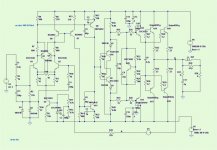
I'm confused - is this not the Krill O/P stage on one of your built prototypes? Taken from here: http://www.diyaudio.com/forums/showthread.php?postid=1717427#post1717427
I'm confused - is this not the Krill O/P stage on one of your built prototypes? Taken from here: http://www.diyaudio.com/forums/showthread.php?postid=1717427#post1717427
Attachments
What has me confused is this post a page back from Os http://www.diyaudio.com/forums/showthread.php?postid=1711801#post1711801
where I interpreted what he says to mean that he has a sliding bias compensating scheme.Q10/9 and the diodes give
you the 4 Vbe's (2.3-2.4v), which is too much(200ma bias per
device) ,Q20 shunts the extra .1 to.2v giving thermal compensation as well (it is mounted on one of the OP devices).
I might use the krill compensation but that would force
me to use 2 trannies and 3-4 diodes to achieve comparable
results.
Another good thing about this is if the Vbe fails, the worst
that can happen is overbiased outputs.
OS
Attachments
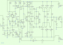
By Jkeny - Is the schematic above posted by you the FA3K schematic?
That is the "K" . it is truly conceptual at the moment as I have
only run its VAS and input stage in the real world.
It has the diamond of the crown 300DC amp, the CCS's of the
krill and the Vbe of the frugalamp. A "patchwork" of sort.
The reason I did not go all the way and use the krill's Vbe
as well is 1. It's diode array and 2 trannies do not track
frequency and amplitude changes as well as the MJE340/bd139,
2. it is easier to implement a single device 3. didn't want to
"rip" Mr. Dunlops circuit.
The actual Crown amp does not use the diamond as t-comp
but instead uses a couple of thermal resistors. Another
Diamond amp, the nakamitchi 620 ,uses a 4 transistor
emitter follower diamond on the main HS as the thermal
compensation .
One errata I do notice with the Diamond buffer is that ,
at high frequency and output,
and without enough current (under 7ma),
small transients will appear at the diamond's
base and emitter. 8 to 10 mA of CCS current solves this, but
this means that the diamond/ CCS array would need a
larger heatsink
 .
.OS
does your amp have sliding biasing, like the Krill
No , you can induce X-over on mine. But after simulating the
krill, by lowering the value of the resistor he has across his
2 diodes , it , too can be made to produce X-over distortion.
In the krill ,if something goes wrong with the diode string
...Deep class A
 and popped fuses. in mine if the MJE
failed ,200ma per device would result.
Both biasing schemes seem to work in a similar way, and,
if properly adjusted, not one iota of X-over dist..
If you want to call that sliding
OS
Attachments
Why I call it sliding bias is that calling it anything with class A in the name gives rise to all sorts of debate about what is/isn't class A. Frankly I don't care what it's called if it sounds good (& there is an understandable operation.)
Anyway, can't the Krill be protected by putting a resistor across the diode string? The krill actively prevents the turn-off of the undriven channel during music reproduction, does yours have some similar mechanism or is it relying on a high bias to prevent class B operation?
Anyway, can't the Krill be protected by putting a resistor across the diode string? The krill actively prevents the turn-off of the undriven channel during music reproduction, does yours have some similar mechanism or is it relying on a high bias to prevent class B operation?
By jkeny -The krill actively prevents the turn-off of the undriven channel during music reproduction, does yours have some similar mechanism or is it relying on a high bias to prevent class B operation?
I don't think the krill works that way, In simulation it works the same as any other class AB amp, one side of the OPS WILL shut off, but only AFTER the other one turns ON.
In true class A both P/N's would pass AMP'S
you would never get 100w+ , as most of the current is used for heat
(tranny + Re) If you grossly overbias mine or the krill ,
true class A will happen at low to moderate OP swing, but
with a lot of dissipation.
Attached I have the .ASC (LT) files for both. If you simulate them,
you will see that my words are true.
OS
Attachments
ostripper said:
No , you can induce X-over on mine. But after simulating the
krill, by lowering the value of the resistor he has across his
2 diodes , it , too can be made to produce X-over distortion.
In the krill ,if something goes wrong with the diode string
...Deep class A
failed ,200ma per device would result.
Both biasing schemes seem to work in a similar way, and,
if properly adjusted, not one iota of X-over dist..
If you want to call that sliding
OS
The addition of a 20K resistor across the diode string will prevent the bias from going over 200mA. I have never seen this failure, but the fix is easy, so why not?
I'm pretty sure that any amp can be made to produce more distortion by deliberately miss adjusting the bias. The distortion will also go up (on my amp) if the bias is set too high. That is the reason I use a distortion meter to set bias.
Thanks for files Os but I don't have simulation s/w yet to run it on - I will be attempting to correct this shortly though. What s/w would you recommend that can be picked up fairly quickly by the less knowledgeable non EE types like myself?
I don't mean to put the two of you at loggerheads but my understanding of Steve's circuit comes from his explanation: Here's Steve's quote for how the biasing scheme works & it seems to me like it's sliding biasing
I don't think the krill works that way, In simulation it works the same as any other class AB amp, one side of the OPS WILL shut off, but only AFTER the other one turns ON.
I don't mean to put the two of you at loggerheads but my understanding of Steve's circuit comes from his explanation: Here's Steve's quote for how the biasing scheme works & it seems to me like it's sliding biasing
The base current in the bias pair is equal in both transistors at all times. I is not, however constant. Changes in the emitter current cause changes in the base current. When one transistor conducts less, the other conducts less. If for example Q8 conducts less because the voltage on the emitter of Q7 goes more positive (causing more current to flow in the base of Q13) then Q11 conducts less causing a greater voltage drop from emitter to collector. This makes more current available to the base of Q15 causing greater conduction to maintain an on state.
ostripper said:
I don't think the krill works that way, In simulation it works the same as any other class AB amp, one side of the OPS WILL shut off, but only AFTER the other one turns on.
Attached I have the .ASC (LT) files for both. If you simulate them,
you will see that my words are true.
OS
I don't doubt what your simulation shows you. My simulations show differently and so have some other peoples. I have also discussed this design in great detail with a number of very good electrical engineers and they agree that it works as I say. The final proof, to me at least, is the building and measuring of several amps at different power levels.
One interesting aspect of this design is that for a given voltage output, reducing the load will automatically raise the bias.
And no, I have not taken any offense at your findings.
I really doesn't matter to me what it is called. It works and more importainly, it sounds good, is stable and reliable.
I don't doubt what your simulation shows you. My simulations show differently and so have some other peoples. I have also discussed this design in great detail with a number of very good electrical engineers and they agree that it works as I say. The final proof, to me at least, is the building and measuring of several amps at different power levels.
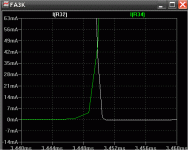
I am a unimformed jerk.. you are right..
(i did not zoom in enough)
the krill's "off side" stays at 3-4 mA ..real class A
neither side goes fully off..
OS
Whew, glad that's all cleared up & no blood spilled in the process!
So that's why I asked about your circuit os, I thought you had a simpler way of achieving this sliding bias. But I guess not, eh!
The Krill biasing scheme, to me seems elegant & worthwhile in that it avoids Xover distortion for any signal no matter how large!
Edit: And doesn't suffer the high wastage of energy that class A operation would entail.
By homemodder - Refer to new class A schemes of the late 70s and 80s.
Any links,, I am bummed out
cheer me up..OS
Hey os don't be bummed out - the work you're doing is superb - keep it up - I was just trying to tease the last drip of performance out of what seems a superb design - problem is I'm no EE & could not even begin to do what you are doing.
Here's a link to a discussion on Technics Newclass A from 2004 resurrected recently - have a look at the recent posters on there http://www.diyaudio.com/forums/showthread.php?s=&threadid=32254&highlight=
Here's a link to a discussion on Technics Newclass A from 2004 resurrected recently - have a look at the recent posters on there
http://www.diyaudio.com/forums/showthread.php?s=&threadid=32254&highlight=- Status
- This old topic is closed. If you want to reopen this topic, contact a moderator using the "Report Post" button.
- Home
- Amplifiers
- Solid State
- The Frugalamp by OS