ostripper said:
There is NO way that a youtube video can be use to perform
a subjective test between amplifiers. The krill is lightyears
ahead of a simple bootstrapped amp (except the aska),but you need audiophile speakers to hear it .., or the difference between fisher consumer
3-ways or peerless drivers in a tuned enclosure.But the krills
better high end might be interpreted as harsh played
through the fishers cheap HF drivers.
OS
I think that there is an option to "waiting for the day" when you purchase $1M audiophile speakers. A prosound equalizer is often a pretty good quality thing, because they're expected to be used at concert volume. But, even a $48 garage band model can be used for a difference tester. In playing a series of half-octave pitches and setting to equal spl, then room, speakers, ears, source, become accurized. Then, just swap the amp. After several go-rounds (average results), you'll have some brand new data about the differences between two amplifiers.
")
What do you think of that?
and that diatribe from one who keeps an active ignore list in his DIYaudio browser.
I think I'm still on his verboten list. You could copy his silly attitude but I recommend you be more tolerant and rise above his level.
Keep the test modifying and listening going. Keep us informed and ignore the puerile comments from the disenchanted others.
I think I'm still on his verboten list. You could copy his silly attitude but I recommend you be more tolerant and rise above his level.
Keep the test modifying and listening going. Keep us informed and ignore the puerile comments from the disenchanted others.
AndrewT said:and that diatribe from one who keeps an active ignore list in his DIYaudio browser.
I think I'm still on his verboten list. You could copy his silly attitude but I recommend you be more tolerant and rise above his level.
Keep the test modifying and listening going. Keep us informed and ignore the puerile comments from the disenchanted others.
Does this mean that you would or would not advise a difference/intelligibility test to be done in addition to electronic testing?
ostripper said:Boy , I have a gripe with the attitude of some forum members.
while rethinking my feelings about this.
Don't worry about it. Learning the engineering fundamentals doesn't prevent you from considering subjective factors if you wish to do so.
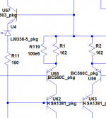
Oh.. some boring VAS "fullup" loopgain plots will follow..
Plot below shows the predicted bandpass plot, but even
on a simple blameless I could not emulate Andy C's VAS
This looks reasonable. Unlike the global loop gain plots, which pretty much all look the same, the local Miller loop gain plots will be all over the map. The one I posted was from a design where the Miller loop gain was purposely made very high in an attempt to reduce distortion. If you're unsure whether or not there is an error somewhere, just post the simulation files, along with a file containing the models you used, and I can look at it.
In this case, there is no frequency band for which the phase is almost constant at -90 degrees, so my previous statement was too broad a generalization, and not always correct. With a bandpass function of this type, you'll see +90 degrees at low frequencies, 0 degrees at about the center frequency, and lagging phase at high frequencies. The bandpass is broad and flat, then it drops off suddenly at high frequencies. There's no region of the high frequency rolloff where it's -6dB/oct, so that's why you never see the region of (roughly) constant -90 deg phase.
Yeah, but have you seen the HF drivers on some of the olderBy DWB -I think that there is an option to "waiting for the day" when you purchase $1M audiophile speakers. A prosound equalizer is often a pretty good quality thing, because they're expected to be used at concert volume. But, even a $48 garage band model can be used for a difference tester. In playing a series of half-octave pitches and setting to equal spl, then room, speakers, ears, source, become accurized. Then, just swap the amp. After several go-rounds (average results), you'll have some brand new data about the differences between two amplifiers.
fisher and sansui 3-ways , FM radio paper cone tweeters..
Even a 12$ (not 1M) pioneer MCM silk dome driver is
a grand improvement enabling you to hear soundstage differences (LTP/CM/CFP). The bass is also suspect, usually
ported to 45-50hz to do "blockparties",VERY noticable..
If you are going to use 4/6/or 8 trannies for your input stage
why not go all the way and drive a decent HF setup
with it.??
by andy C. - Don't worry about it. Learning the engineering fundamentals doesn't prevent you from considering subjective factors if you wish to do so.
It just disturbed me slightly..
... I'm glad my loop gain testis not totally incorrect.. I even subbed LG2.asc for LG1.asc
in a global plot to compare results. I will post my latest .asc with
models used.
The bandpass response makes sense , but the gain of the
plot is suspect..I am truely in both camps as I will end up using
a simulated design in real life, but I don't want have to sub
every compensation cap in my parts box to get in the "ballpark".
By DWB - Does this mean that you would or would not advise a difference/intelligibility test to be done in addition to electronic testing
Yes, but with a 320kbs audio/divx video clip or a flac/wav recorded output using a HQ microphone.. not 128kb/s
flash AV using a webcam.
Definitely , Mixing sound engineering with reality is best.By Andrew T. - Keep the test modifying and listening going. Keep us informed and ignore the puerile comments from the disenchanted others
It was said a"blameless" sounded like C#@P , so now I have
bootstrapped ones with the added benefit of a CCS/CM,FA1b
(oooh... boring)
I could start a speaker factory with that..I think that there is an option to "waiting for the day" when you purchase $1M audiophile speakers
I replacedmy sony 3-way cheap tweeters with -
http://www.mcmelectronics.com/product/MCM-AUDIO-SELECT-53-526-/53-526
and the detail/soundstage improvement was far greater than
any change in amp topology.
OS
Attachments
ostripper said:
There is NO way that a youtube video can be use to perform
a subjective test between amplifiers. The krill is lightyears
ahead of a simple bootstrapped amp (except the aska),but you need audiophile speakers to hear it .., or the difference between fisher consumer
3-ways or peerless drivers in a tuned enclosure.But the krills
better high end might be interpreted as harsh played
through the fishers cheap HF drivers.
OS
OK, I'm blushing. You have said some very nice things about my amp. I started following this thread because I like amp design. I kept following because of the knowledgeable people posting here. This has been an excellent place to pick up more knowledge on simulations. My amp was designed, built an tested the old fashioned way. I used test equipment. I knew it worked and tested very good. I did not let that deter me from trying to simulate it as soon as I could get my hands on the software.
Listening to music is ultimately what this is about. I listed to what I build and attempt to evaluate and make sense of what I hear. I would never dream on NOT testing an amp because it sounded good. Likewise, every time I made changes that improved performance in either distortion or noise floor, I have fooled myself into thinking the sound was improved.
Simulation is one more tool we have to help us design. I would never want to go back to no sims. It is true some circuits may not simulate correctly or at all, but this is sometimes the operator not the software. I have found simulation to be especially useful when a working design can be duplicated. At this point it is much more practical to adjust component values for optimum performance than by changing each component and trying to measure or hear the very small difference it made.
Just my opinion.
ostripper said:The bandpass response makes sense , but the gain of the
plot is suspect..
I checked it, and it looks fine. It did surprise me that it wasn't higher than this, but the VAS loop gain isn't real easy to guess. I noticed when putting large bypass caps on the VAS emitter resistors, it got quite a bit higher as expected. The VAS is plenty stable in either configuration.
Dunno. For input stage frequency response, I usually look at it by itself, loading the input stage current mirror (if present) with a DC voltage of around 1.4 Volts from the appropriate supply, then look at the frequency response to the current through that source. It's hard to talk without schematics though. If the input stage has a CFP, I've seen that problem too, and not been able to get rid of it.
Input stage has cfp yes, so its a common problem. Does it show up with real circuit too or is it simm problem?? I have no equipment to do real testing with me now till my container comes from my previous home which was 14 000 km from where Im now.
My ltp looks very much like os s circuit but it does have current mirror. I havent been able to cure it either.
My ltp looks very much like os s circuit but it does have current mirror. I havent been able to cure it either.
homemodder said:Input stage has cfp yes, so its a common problem. Does it show up with real circuit too or is it simm problem?? I have no equipment to do real testing with me now till my container comes from my previous home which was 14 000 km from where Im now.
I don't know whether it goes away in the real world, as I avoided the technique because it behaved poorly in the sim.
A messy technique for stabilizing it which you might be able to simplify was presented in this thread. I haven't tried it in the sim or real life.
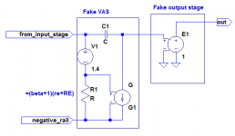
One thing I did find with experiments in the sim was that the common-mode input stage distortion dominated over difference-mode, by more than an order of magnitude. I did this by modeling the VAS as an idealized transconductance (VCCS) with a Miller cap, and the output stage an ideal VCVS. See pic below. So I think the reduction of simulated distortion by using CFPs in the input stage is to a large extent a quirk of how they handle common-mode effects. The bootstrapped cascode with ordinary input diff pair does surprisingly well, as long as the degeneration resistors aren't tiny.
Attachments
Thanks andy, I read that tread more carefully, although I have serious doubts about that vas, Ive tried it real life and couldnt get it stable although theres a yamaha amp that uses it. Mine has high loop gain too but no baxandall for me, can be achieved by other means. Ill try some comparison tests without the cfp.
homemodder said:Thanks andy, I read that tread more carefully, although I have serious doubts about that vas...
Me too. I just remember having seen that funky compensation scheme for the input CFP, so I thought I'd pass it along.
by andy C.So I think the reduction of simulated distortion by using CFPs in the input stage is to a large extent a quirk of how they handle common-mode effects.
CFP inputs are cool.. the Ic ratio between P and N is
a tradeoff between noise and linearity. I found that a
equal balance in Ic (.9Ma PNP+ .9Ma NPN - FA3) almost totally cancels H3 with a marginal/acceptable increase in noise.
The advantages surprised me after exhaustive simulation,
the loading of the LTP seemed immune to frequency unlike
the common pair before.(lower Gm)
I don't seem to get any peak or unstability either.
I noticed changes in UG/phase as I varied bypass caps betweenBy andy C. - I noticed when putting large bypass caps on the VAS emitter resistors,it got quite a bit higher as expected
.68u and 10u ,even more change than Cdom. I made universal pads on my final board to allow for any device.
OS
Hi man!
I didn't mean any disrespect at the previous post that was about comparisons of amplifiers. Actually, I was thinking of these materials: http://www.meyersound.com/support/papers/speech/glossary.htm And, just how hard it would be to get all of the "other" factors under control in order to be able to "hear" the amplifier.
I didn't mean any disrespect at the previous post that was about comparisons of amplifiers. Actually, I was thinking of these materials: http://www.meyersound.com/support/papers/speech/glossary.htm And, just how hard it would be to get all of the "other" factors under control in order to be able to "hear" the amplifier.
I would guess that the technique of running an amp through
a 300R resistor to a pair of quality headphones is
most unbiased and would eliminate many secondary effects
for a subjective evaluation of 2 amplifiers.
OS
PS ..you did not offend, for if you did I would of expressed my
distaste vehemently.
a 300R resistor to a pair of quality headphones is
most unbiased and would eliminate many secondary effects
for a subjective evaluation of 2 amplifiers.
OS
PS ..you did not offend, for if you did I would of expressed my
distaste vehemently.
ostripper said:
CFP inputs are cool.. the Ic ratio between P and N is
a tradeoff between noise and linearity. I found that a
equal balance in Ic (.9Ma PNP+ .9Ma NPN - FA3) almost totally cancels H3 with a marginal/acceptable increase in noise.
The advantages surprised me after exhaustive simulation,
the loading of the LTP seemed immune to frequency unlike
the common pair before.(lower Gm)
I don't seem to get any peak or unstability either.
I noticed changes in UG/phase as I varied bypass caps between
.68u and 10u ,even more change than Cdom. I made universal pads on my final board to allow for any device.
OS
Hi,
I can confirm your results in my simulations about tuning out
2nd and 3rd harmonic in a CFP front-end.
See post:
www.diyaudio.com/forums/showthread.php?s=&postid=1707415#post1707415
I also got rid of the "messy" compensation on the CFP.
Mike
By MFC - I can confirm your results in my simulations about tuning out 2nd and 3rd harmonic in a CFP front-end.
I am glad to hear you like it.I just completed the real front end
and powered my FA2's Op stage with it... It works..and
very good!!!
To show my confidence in this tom holman inspired circuit,
FA3 is ready to share..
http://71.203.210.93/pdf1/Electronics/Projects/Audio_amp/Frugalamp/
The file is "FA3_full.zip" and is complete with PCB (600dpi),
BOM,parts placement,simulation, and schematic /w currents.
I have a feeling this topology will become my standard
"houseamp" and by running my peerless sub I might
make a high powered version of it...(FA3 B or 4??)
All "frugalamps" are always available and updated in the
"Electronics/Projects/Audio_amp/Frugalamp" folder, just
click my "WWW" button..
OS
- Status
- This old topic is closed. If you want to reopen this topic, contact a moderator using the "Report Post" button.
- Home
- Amplifiers
- Solid State
- The Frugalamp by OS