AndrewT said:Andy,
if the gain of these amps we're analysing were all +20dB (10times) then the GBW product would be in the range 8MHz to 12MHz. Is that correct?
Yes, that's exactly right. Looks like OS's latest creation has a gain of 28, so that gives it about a 28 MHz GBW product.
Now that I am there, what do I do with the unity loop gain graph to check stability?
Do I find where Gain intersects with Plot and read off frequency and at that frequency read off the phase to be subtracted from 180degrees?
Or should I be using the GBW product graph to extract the phase margin?
The easiest way to determine stability is to find the phase margin from the loop gain plots. To do this, find the unity loop gain frequency (where the magnitude of the loop gain is 1x, or 0 dB). Find the phase shift phi at that frequency. Take that number and subtract negative 180 degrees from it. OS and others have been targeting phi = -100 deg at the ULG freq. So the phase margin PM in this case is:
PM = phi - (-180) = -100 - (-180) = 80 degrees
IOW, the phase margin is how far the phase shift of the loop gain at the ULG freq is from -180 deg.
Assuming the input LPF is disabled and there is no lead compensation cap in the feedback loop, a PM of 90 degrees will give a small-signal step response that looks just like a first-order LPF. A PM of 78 degrees for a second-order system gives a critically-damped step response. A phase margin less than 78 degrees in a second-order system gives overshoot and/or ringing in the small-signal step response. An oscillator is designed to have a phase margin of exactly zero degrees.
bY andy C. - Hmm, okay. But what you posted here as the result is not the loopgain2.asc technique. That's what threw me off. I can tell because of the -V(d)/V(c) expression. loopgain2.asc uses both voltage and current injection (Ii and Vi) and uses this formula for the loop gain:
It was harder but "doable". my question is would you use
loopgain.asc 2 as the test of choice for plotting
gain at global NFB as well ?? I see its value for plotting a
nested loop within the whole but use it for the global test.. too?
I did this on my fa3 with LG2's probes between Cdom(S) and-1/(1-1/(2*(I(Vi)@1*V(x)@2-V(x)@1*I(Vi)@2)+V(x)@1+I(Vi)@2))
VAS out as was shown . the resulting plot was reversed (inverted)
I then changed where "X" was placed and plotted the
typical "skislope" plot starting at 90db and decaying with
freq.
Jaycee, I will attach your ASC at end of post with the models I used..
OS
Attachments
ostripper said:It was harder but "doable". my question is would you use
loopgain.asc 2 as the test of choice for plotting
gain at global NFB as well ?? I see its value for plotting a
nested loop within the whole but use it for the global test.. too?
For global loop gain, I use the simplified way myself, just because it's easier. But there's many things that can trip up this technique. As long as you're aware of these, it's fine. For example, connecting a lead compensation cap from VAS output back to the inverting input of the amp creates another feedback loop. To see the loop gain of that inner loop, one must move the probe element(s) inside the inner loop. But if you try this with the simplified method of just a voltage source, you'll violate the assumption under which its approximation is accurate - namely that one side of the voltage source looks like zero impedance to ground (e.g. the amp output).
So as long as you're aware of the limitations, it's fine.
I did this on my fa3 with LG2's probes between Cdom(S) and VAS out as was shown . the resulting plot was reversed (inverted) I then changed where "X" was placed and plotted the typical "skislope" plot starting at 90db and decaying with freq.
It's hard for me to visualize what you did. The "X" node should be at the junction of Vi and Ii, rather than on the other side of Vi. I usually just open up the loopgain2.asc, use F6 to copy the probe elements, then Ctrl-V to paste into my schematic. This renames the probe elements to "Vi1" and "Ii1", so I have to rename them back to "Vi" and "Ii" by right-clicking on the text. That way I don't mix the orientation up or have to retype the expressions u(prb) and so on. The way the complex formula works out, you can flip the whole probe around either way with Ctrl-E and it works exactly the same in either direction.
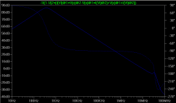
For the VAS loop gain, you can spot errors by observing that, if correct, it looks like a bandpass filter, and that its phase is approximately constant at -90 deg after it starts rolling off at high frequencies. It's just like the global loop gain in that respect. Here's an example VAS loop gain plot.
Attachments
By homemodder - This design is very finiky of a fast outputstage
That is why I moved on (..back.."balanced blameless")to FA3.
Fa2 (cyrus without CFP) is working right now in my HT. I
tamed it by shunt compensating the output of VAS (like mike B's symasym). Most designs like the FA2 or symasym also use
older/ slower devices with higher Cob and lower Hfe
(symasym - 2n5401 most others - mpsa92/42 or mje350/340)
Jaycee's VAS is a Lender design (with the diode) and should
be compensated like in the attached diagram.
OS
Attachments
is the second stage PNP really that, or is it an NPN?ostripper said:Jaycee's VAS is a Lender design (with the diode) and should
be compensated like in the attached diagram.
It's not the same. The VAS is identical to the symasym style one, the differences are the current mirror and one side's load. The diode simply provides the same sort of voltage drop as a diode-connected transistor. The differences are mostly to do with thermal balance.
The instability isn't in the VAS anyway, it's in the input stage.
Really, what I need to do is build it, but without a 'scope i'd be guessing. I'm annoyed that I missed out on getting a Telequipment DM64 'scope from freecycle last week!
The instability isn't in the VAS anyway, it's in the input stage.
Really, what I need to do is build it, but without a 'scope i'd be guessing. I'm annoyed that I missed out on getting a Telequipment DM64 'scope from freecycle last week!
It's not the same. The VAS is identical to the symasym style one
I just used the D.self drawing for an example. To clarify this as I have modded mine both ways, In the symasym.. (FA2..what I have now)2 capacitors in the VAS cause instability (oscillations) . I have
found in both versions only one cap (cdom),with the diode or
CM version, offers more stability (I have
scoped it and felt warm zobel's with 2 Cdoms)
the VAS behaves much differently between the diode and true
CM versions in regard to compensation and gain.Make a board
with extra pads or veroboard it to "play".
The CFP on my new one (FA3) is really good and does not have
the excessive gain as does the cyrus one..good luck.
OS
The problem is indeed with the inputstage, its very high gain and speed doesnt combine well with the vas, in the cyrus a different vas is used, less gain and in that application it works fine, I have simmed the cyrus, no problem with compensation there although a different scheme brings better results.
Boy , I have a gripe with the attitude of some forum members.
 In fact I haven't posted for a while
while rethinking my feelings about this.
Here is the quote that offends...
that thread )
)
I suppose the literature on the semiconductors we use is
also irrelevant...!
Should I feel guilty for using the tools available to design
a better mousetrap.I actually do build them after simulation
as well as share the build afterwards.
A good argument can be made that a simulation cannot
predict the final sound , but boy, one can fine tune
the circuits basic electrical characteristics thus avoiding a silicon
graveyard (D. Self analogy).
And to contradict this next one...
ALL you "instrumentologists" and boring people
please come to calculate and "sim" away. If not for these
"boring people" there would be no thread or forum or computer
or DMM or anything for that matter. And maybe the cloudy folks
did not have to build 4000 amplifiers to get a few right .
Oh.. some boring VAS "fullup" loopgain plots will follow..
Plot below shows the predicted bandpass plot, but even
on a simple blameless I could not emulate Andy C's VAS
OS
PS .. We are here to learn , and if you do not grasp the fundamentals you and your hobby are dangerous.
In fact I haven't posted for a whilewhile rethinking my feelings about this.
Here is the quote that offends...
(we know who this is...and that is why I never DIY'ed fromMeasurements, charts, technicall evaluations, graphics, spectrum analisers results, distortion results, linearity graphics, angle graphics...all that will serve only to your personal fun and to ATTRACT boring "instrumentologists" to come here and invade a nice thread made by someone evaluates listening, and they will come to say good things or bad things when all they can say I already know listening...and this is what matters to me.
that thread
)I suppose the literature on the semiconductors we use is
also irrelevant...!
Should I feel guilty for using the tools available to design
a better mousetrap.I actually do build them after simulation
as well as share the build afterwards.
A good argument can be made that a simulation cannot
predict the final sound , but boy, one can fine tune
the circuits basic electrical characteristics thus avoiding a silicon
graveyard (D. Self analogy).
And to contradict this next one...
Even if my amplifiers measure wonderfull or awfully... i am personally absolutelly not interested, and i am sure will attract boring people to this thread...... we have 3 of them in our forum... cloudy folks!
ALL you "instrumentologists"
and boring peopleplease come to calculate and "sim" away. If not for these
"boring people" there would be no thread or forum or computer
or DMM or anything for that matter. And maybe the cloudy folks
did not have to build 4000 amplifiers to get a few right
.Oh.. some boring VAS "fullup" loopgain plots will follow..
Plot below shows the predicted bandpass plot, but even
on a simple blameless I could not emulate Andy C's VAS
OSPS .. We are here to learn , and if you do not grasp the fundamentals you and your hobby are dangerous.
Attachments
Don't want trouble ,but BS is BS. Anytime I have ever commented
in this thread, (even without being boring) very unwelcome response , questions unanswered. A very exclusive club...
http://www.diyaudio.com/forums/showthread.php?s=&postid=1703840#post1703840
(post 1309)
Wrong spirit for DIY
OS
in this thread, (even without being boring) very unwelcome response , questions unanswered. A very exclusive club...
http://www.diyaudio.com/forums/showthread.php?s=&postid=1703840#post1703840
(post 1309)
Wrong spirit for DIY
OS
Os I have one foot in both camps, Its important what a amp sounds like but one has to go about this with sound technical design and reason.
Look at how carlos found out that the muse caps are better sounding than normal caps, they measure much better too so his theory of measures better sounds worse is often out of place, this happened some time back ago with the self blameless design too, at first he hated the sound, after the second build he changed opinion somewhat I would certainly care if my amps were oscilating or showing any other abnormal or compromising operating characteristics. I think Carlos should compare less amps to each other, they all sound different, and visit concert halls more than compare the amps with real life, I think he will have some surprises. What pleases his and others ears is often not what real sounds, sound like.
Somewhere in a thread he placed a little youtube clip comparing his dx to the krill amp, saying theres not much diffrence, heck he recorded this with a camera but even so I could clearly hear a huge improvement with the krill amp, I bet that amp measures significantly better too.
Look at how carlos found out that the muse caps are better sounding than normal caps, they measure much better too so his theory of measures better sounds worse is often out of place, this happened some time back ago with the self blameless design too, at first he hated the sound, after the second build he changed opinion somewhat
I would certainly care if my amps were oscilating or showing any other abnormal or compromising operating characteristics. I think Carlos should compare less amps to each other, they all sound different, and visit concert halls more than compare the amps with real life, I think he will have some surprises. What pleases his and others ears is often not what real sounds, sound like.Somewhere in a thread he placed a little youtube clip comparing his dx to the krill amp, saying theres not much diffrence, heck he recorded this with a camera but even so I could clearly hear a huge improvement with the krill amp, I bet that amp measures significantly better too.
Thank you ,mlloyd. I try not to be too opinionated, but I
would like to put very well planned and documented DIY
material within even the beginners reach.
I personally would always try to answer any question from
the most basic all the way to the technical end of the spectrum.
That is the primary purpose of this forum, at least as far as I
am concerned. To remove the technical aspect of design
is to be blind, perhaps a DMM is for instrumentologists and we
should just "plug it in".
MJL and GK are by far the best constructors here (1 man factories) and have been helpful and not "boring".
I guess I'll get over it and build my next amp , give it a new
exciting name , like "THDXERO MK1" ...since substance
always takes a back seat to image.
OS
homemodder said:... Somewhere in a thread he placed a little youtube clip comparing his dx to the krill amp, saying theres not much diffrence, heck he recorded this with a camera but even so I could clearly hear a huge improvement with the krill amp, I bet that amp measures significantly better too.
I am certain the Krill is better also
Ostripper and John you both have my absolute appreciation for what you are both trying to achieve. You both have very interesting threads, IMHO, and Carlos's comments are really not appropriate ... quite amazing, actually

So please, both of you, keep on, keeping on
thanks
By Homemodder-heck he recorded this with a camera but even so I could clearly hear a huge improvement with the krill amp, I bet that amp measures significantly better too.
There is NO way that a youtube video can be use to perform
a subjective test between amplifiers. The krill is lightyears
ahead of a simple bootstrapped amp (except the aska),but you need audiophile speakers to hear it .., or the difference between fisher consumer
3-ways or peerless drivers in a tuned enclosure.But the krills
better high end might be interpreted as harsh played
through the fishers cheap HF drivers.
OS
True but even with less good speakers one can hear what a amp is about, take a careful listen, one can clearly hear that the krill, has more controlled bass, increased detail and open midrange, that tells me the whole story. I wont comment on the highs as this is impossible with those speakers. That krill must be quite a fast amp. I listened with my hd600 seinheisers.
- Status
- This old topic is closed. If you want to reopen this topic, contact a moderator using the "Report Post" button.
- Home
- Amplifiers
- Solid State
- The Frugalamp by OS