@Joe Rasmussen following up on mito147 point of any solid state amps that you’ve heard paired with the Elsinores, which have really impressed you or very positive feedback from Elsinore builders.
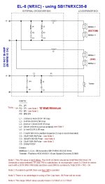
I would say that the best solid state power amp I have heard so far is the March Audio P262 fitted with Purifi Eigentakt Class D modules. My own amp is a 'hybrid' in reverse. The common hybrid is tube frontend with solid state output stages. So mine is the reverse what others have done. The great Richard 'Dick' Sequerra told Allen that the greatest tube of all time is the EL34. If that is the case, then it should be wired as s Pentode, but rarely done. But Dick left something out and it took me years it to figure out. And as he was keeping it secret, I will for a while also (sorry). His solution was global feedback (it needs it), but I found a way to use local feedback, but the key is how you treat the Screens. But the impedance values you end up using is much higher than you think and instead of it rolling off the tube at HF, it doesn't. Get it right and you have the only output stage that makes music sound magic.
I am lucky, I have several musicians in my family, for most of my life I have lived in a house with a really good piano (I am biased towards Yamaha, but we have had Kawai and others). My wife is a player, but both my son and my brother-in-law are high quality players, my son is now a piano teacher and some of the dynamics he produces on the fifteen grand large Yamaha upright we have right now, it does has to be heard to be believed. What my son does is create monstrous and spine chilling dynamics and his mate who plays the cello sometimes comes around and it sounds like it can cut through doors when listening from the other side. These are sensations that HiFi systems don't do, not ordinarily. And power amplifiers compress these dynamics and the seems no reasons why they should. They can supply power and lots of it, but there is a big difference between power and dynamics. I am right now listening to an amp that does not seem to compress those dynamics at all and rated at 32 Watt into the Elsinores. You can even hear it when not playing loud, but then might become fun when you do increase the volume. But I sound like ranting, but anybody can come around for a listen, I am here 90% of the time.
Here is one of my favourite Sequerra stories, told in an interview:
Is that what he meant?that the greatest tube of all time is the EL34. If that is the case, then it should be wired as s Pentode, but rarely done.
Allen, I hear you, but there was more to the conversation. If a tube is proclaimed 'the best' and it is a Pentode, then it is clear that if it was designed as a Pentode, then the person proclaiming it 'the best' had in mind that it be used as a Pentode. Otherwise where is the logic. Now others may disagree as to which power tube is 'the best' of all time and why and I don't have any issues about that. But that declaration re EL34 by Sequerra, it set in motion what is now history, to get the EL34 sounding as good as possible and it turns out amazing. Connect those Screens to the Anode and the dynamics and sheer liveliness disappears. Connected it to taps on the transformer, and it sounds crude and messy, but more lively. Wire the Screen correctly (the Screens needs to see a certain condition and maybe you can guess it?) and potential magic happens. But Pentode needs some feedback, Sequerra used global, but local is so much better, but that presents challenges too.
This goes for most people who design anything and in this case an amplifier, there is a history (or just a plain story) how you got to the end result, and it is rarely a straight road. Every design that gets results in the end, has a story to tell, right?")
This goes for most people who design anything and in this case an amplifier, there is a history (or just a plain story) how you got to the end result, and it is rarely a straight road. Every design that gets results in the end, has a story to tell, right?
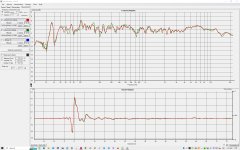
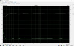
A friend of mine built Elsinore speakers a few years ago, all exactly to design. Drivers are SB17NRXC35-8 and Scanspeak D2608/913000. We have recently measured the frequency range at 1m in the axis of the tweeter. Both speakers are pretty much the same (red and green lines).
It can be seen that the range between 4kHz and 8Khz is raised a lot (+5dB at 6kHz) and that after 13kHz it drops sharply (-5dB). This response creates sharpness in the sound, while at the same time small details are missing. Any idea how to fix it?
It can be seen that the range between 4kHz and 8Khz is raised a lot (+5dB at 6kHz) and that after 13kHz it drops sharply (-5dB). This response creates sharpness in the sound, while at the same time small details are missing. Any idea how to fix it?
Attachments
We have recently measured the frequency range at 1m in the axis of the tweeter
Sorry: You have measured them incorrectly!
Your measurement actually looks good to me. Because it is what I would expect.
They should be measured at 2 metres and 15° Off Axis. That is what they were modeled and designed for, that angle and and that distance.
I am current working on a 2-Way speaker system using a TeXtreme cone driver (very expensive) and here is the modeling for On Axis, 15° Off Axis and 30° Off Axis, and this is what it looks like, again at 2 metres and not 1 metre:
I can assure you, if following my instructions, try to put speakers with tweeter to tweeter 2.5m wide, toe in so that you listen at 15° Off Axis. They will not sound sharp nor bright.
According to Van Dickason the power response into the room is largely the response at 30° Of Axis, and by that definition, the TeXtreme coned speaker, and the Elsinores too, cannot be regarded as bright sounding.
A speaker has many frequency responses, every time you change the position of the microphone, you will get another frequency response. Howe many do you want? But there is only one power response into the room, and that should IMHO be descending. That applies to the Elsinores and the speakers I am working on now.
If you put it into a bright room, the all loudspeakers will sound bright. I've had to design speakers that worked in small and over-damped rooms. When taken into normal rooms, they will sound bright because they were designed to work in a room with a lot of damping and padding. So the room does matter too. Thankfully I have a very well balanced room and I hate artificially bright speakers.
This response creates sharpness in the sound, while at the same time small details are missing. Any idea how to fix it?
Is that really what you are hearing? Sorry, but they don't need fixing. And your measurement is what I would expect when 1 metre and On Axis. But that does not tell you the complete story. Get equipment with higher resolution (most commercial amplifiers are not that good, IMHO) or a better source. And I get the feedback all the time, better source and amp, and the Elsinores jump up meet the challenge and now sounds better that they imagined that they could. I am not saying this, this is the feedback that I get from end users. And it makes me feel good.
If possible, can you repeat the measurement. I know that doing 2 metre measurement is about four times harder than doing it an 1 metre, so may I suggest at least 1.5 metres. Now put the microphone 15° degress Off Axis, and let us see what it looks like.
I am in fact a low distortion person, so the response in the very top octave 10-20KHz does not obsess me.
Last edited:
"EL-6_Traces.gif" is modeled and not measured. The dip that you see is a result of the behaviour of the NRX cone and gives what some say is a BBC dip. I am neither a critic or promoter of the BBC dip. But actual measurements at distance and angle changes the result somewhat.
But I think I can help you add a tweak that you might want try. Please read on. On the same web page you should also have seen this:

This 1/6th Octave was taken with both speakers 2.5 metres apart (centre of tweeter to centre of tweeter) and also 2.5 metres to the position of the microphone. Equal triangle, pink noise and microphone at tweeter high, the speaker angled in but not pointing at the listener, about 15° Off Axis.
The two peaks near the bass plus the trough at 300Hz are room modes.
The tweak you could try is a 33R 5 Watt decent quality resistor fitted in parallel with L3/C2, to ground. This will pull the response down slightly and of course you can tweak that value, but no lower than 22R. This was done in the ULD version of the Elsinores. The MFC version does not need it, but you could try it with the NRX version and report back here.

You might also be interested in this: Take a look below, this is the NBAC Elsinores that I have now finished but not yet published, but very soon (I have had some major distractions lately and it should have been published a month ago otherwise):

The NBAC with ceramic coated aluminium tweeter, it needed this response slope. This is because it behaves differently from a silk dome tweeter and so this affects the balance.
Below is the ULD measurement (with subs):

Compare the fact that this is with a soft dome tweeter and the balance is accordingly different than a hard dome. The latter's greater acceleration to the ear (perceived acceleration) makes it sound more prominent. It has to be handled differently. Some have called this kind of thing part of voicing the speaker, but I prefer balancing instead.
Even though different drivers, you can see that when set up as as a 2.5 metre equal triangle and 15° appprox and not on axis, this is the latest result of the NBAC Elsinores. Again, you can see the same room modes near LF, even though this is a different version of Elsinores.
Now the ear is not able to hear the frequenecy response as we see it above. So for added interest, I repeated the exact measurement, but not 1.6th octave, but a full octave:

This is more like the balance we that we are likely to hear. You can still see the room modes, that is clear, a couple of dB in a single octave is audible for sure. So this measurement is certainly of interest as it gives us some context closer to the real world.
Finally, this is my 3-man couch below and the setup for doing pink noise RTA tests. The two persons on either side will hear more on axis response of the speaker that is nearest and more off axis (and further away) of the other side. So as one gets 'hotter' the other goes 'colder' and so the three listeners end up with similar balance that they hear. Of course, only the centre listener with get an accurate stereo image ("you can't change physics" - said by Roger Sanders in a phone conversation). But you can do measurements at all three listening positions and get reasonable correlation. As one goes further off axis, the other goes further on axis. Neat, if I may say so myself.

Now if you got to the end, may I suggest reading it a second time. It will make more sense the second time.
But I think I can help you add a tweak that you might want try. Please read on. On the same web page you should also have seen this:
This 1/6th Octave was taken with both speakers 2.5 metres apart (centre of tweeter to centre of tweeter) and also 2.5 metres to the position of the microphone. Equal triangle, pink noise and microphone at tweeter high, the speaker angled in but not pointing at the listener, about 15° Off Axis.
The two peaks near the bass plus the trough at 300Hz are room modes.
The tweak you could try is a 33R 5 Watt decent quality resistor fitted in parallel with L3/C2, to ground. This will pull the response down slightly and of course you can tweak that value, but no lower than 22R. This was done in the ULD version of the Elsinores. The MFC version does not need it, but you could try it with the NRX version and report back here.
You might also be interested in this: Take a look below, this is the NBAC Elsinores that I have now finished but not yet published, but very soon (I have had some major distractions lately and it should have been published a month ago otherwise):
The NBAC with ceramic coated aluminium tweeter, it needed this response slope. This is because it behaves differently from a silk dome tweeter and so this affects the balance.
Below is the ULD measurement (with subs):
Compare the fact that this is with a soft dome tweeter and the balance is accordingly different than a hard dome. The latter's greater acceleration to the ear (perceived acceleration) makes it sound more prominent. It has to be handled differently. Some have called this kind of thing part of voicing the speaker, but I prefer balancing instead.
Even though different drivers, you can see that when set up as as a 2.5 metre equal triangle and 15° appprox and not on axis, this is the latest result of the NBAC Elsinores. Again, you can see the same room modes near LF, even though this is a different version of Elsinores.
Now the ear is not able to hear the frequenecy response as we see it above. So for added interest, I repeated the exact measurement, but not 1.6th octave, but a full octave:
This is more like the balance we that we are likely to hear. You can still see the room modes, that is clear, a couple of dB in a single octave is audible for sure. So this measurement is certainly of interest as it gives us some context closer to the real world.
Finally, this is my 3-man couch below and the setup for doing pink noise RTA tests. The two persons on either side will hear more on axis response of the speaker that is nearest and more off axis (and further away) of the other side. So as one gets 'hotter' the other goes 'colder' and so the three listeners end up with similar balance that they hear. Of course, only the centre listener with get an accurate stereo image ("you can't change physics" - said by Roger Sanders in a phone conversation). But you can do measurements at all three listening positions and get reasonable correlation. As one goes further off axis, the other goes further on axis. Neat, if I may say so myself.
Now if you got to the end, may I suggest reading it a second time. It will make more sense the second time.
Last edited:
We will try that of course, thank you. And a new measurement. The listening position is at about 3.5m from speakers, so we will measure it all. It's not my speakers so I can't do it right away but it will be soon.The tweak you could try is a 33R 5 Watt decent quality resistor fitted in parallel with L3/C2, to ground. This will pull the response down slightly and of course you can tweak that value, but no lower than 22R.
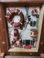
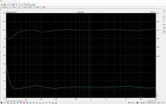
Phase and impedance are as per your design as far as I can see. My friend has a transistor amplifier, so it doesn't matter that much to him. It was recorded more as a check that everything was done correctly.
Attachments
Last edited:
That flat impedance may not seem important when using a transistor amp? Actually, it does sound wise. More designers are becoming more aware that it actually sounds better for it. For some reason some consider this controversial, because it means something must be happening on the current side and as a result of this interface, not on the voltage side (are you listening Allen), but on the current side. But the proof is in the pudding.
Find a 2-Way speaker rated as 8 ohm. If you can, check if there is a peak in the Impedance somewhere near 2KHz and that it is often over 30 Ohm. Now get a 8R2 10W cheap ceramic resistor and put it in parallel, both speakers are now nominally 4 Ohm and not 8 Ohm any more. Now listen. Now in the critical midrange most of the current is going through the resistor - 8R in parallel with 30R and most of the current will go through the resistor and not the speaker. Any reactive current (that's another topic) created will now be less able to pollute or alter the current of the amplifier. This means that the force factor inside the motor of the driver is less "noisy" and I said that nearly ten years ago and I was attacked mercilessly. Interestingly the "noisy" word is now used by Michael Børresen when discussing his non-ferrous drivers. Yes, he says that chasing down noise in the driver is a big deal - note that this noise exists on the current side of the amplifier (right Allen).
Many won't know who Michael Børresen is, so here is a link, but warning, the prices are eye watering:
https://www.audioholics.com/bookshelf-speaker-reviews/boerresen-acoustics-m1
I'm here.. but I was first thinking about the issue @NIXIE62 is facing.not on the voltage side (are you listening Allen), but on the current side.
tmuikku discovered a power peak in the 4-8kHz region which may for example change with varying ceiling height and speaker listening distance.between 4kHz and 8Khz is raised a lot
This approximation won't be suitable where you use multiple midranges or a crossover.According to Van Dickason the power response into the room is largely the response at 30° Of Axis,
Last edited:
I just said it doesn't matter that much, not that it doesn't matter at all. I mean, with some SE tube amplifiers with a higher output impedance due to the output transformers (1-3 ohm), you will easily hear a disturbance in the frequency range due to the variable speaker impedance. With a transistor DC coupled amplifier of low output impedance this will not be heard, but something else may be heard because the peak impedance is reactive. I have not really studied these problems in detail, I admit.That flat impedance may not seem important when using a transistor amp?
Don't worry, it's my job to make the speaker sound good on all amps and not just do things to make tube amps sound better because they have higher output impedance. My goal is that the current drawn from the amplifier should be the same at all frequencies and that it benefits every kind of amplifier.
I note you edited this. No, I don't recall Vance saying such a thing. I don't use it as a strict guide myself and you make a fair point. I just use it in conversations where I want to point out that if you are interested in the power response (as there is only one), then we should look at what the speaker does off axis and not on axis. I think that is also a fair point to make.
This approximation won't be suitable where you use multiple midranges or a crossover.
I note you edited this. No, I don't recall Vance saying such a thing. I don't use it as a strict guide myself and you make a fair point. I just use it in conversations where I want to point out that if you are interested in the power response (as there is only one), then we should look at what the speaker does off axis and not on axis. I think that is also a fair point to make.
Yes. I originally wrote..I note you edited this.
Did Vance mention this approximation isn't suitable where multiple midranges are, or where a crossover is used?
No, I don't recall him saying that. But I take point you made. Makes me think about the behaviour of long vertical line sources and the fall-off being 3dB and not 6dB, things do change, but I have not made any deep analysis of that.
Below I will describe what is important to me and why a bit of rise in on axis of the response is not always bothersome and looks like this:

Green On Axis, Red 15° Off Axis and Brown 30° Off Axis.
Note the fact that this is a point source vertically aligned, and also note that I measure them at 2 metres where they 'come together' and they don't at 1 metres, I pay very close to the off axis response where the listener is at least 2 metres away. Did you see my 3-man couch diagram?

None of the three listeners are listening to the direct on axis response. The person on the left is here more of the on axis of the left speaker and still 5° off axis. And this is compensated by the fact that the right speaker is now near 30° of axis.
As I move to one side, the nearest speaker gets you further on axis, but not full on axis. The response will rise. The speaker on the other side, you are now listening even more off axis. There the rise has reversed. There is a compensation mechanism going on and that the sum/balance is quite consistent by all three seaters.
To prove it, I will do the three measurements at the three seated positions and post them, left, centre and right RTA 1/6th octave measurements. I do believe the fact that they will look pretty good and consistent, that it proves my approach to be correct. It explains why I can tolerate a rising top on axis. I have put a lot of thought into this.
BTW, if that rise is only on axis of the mid driver and falls of when going off axis and that the CSD looks fairly clean with no pronounced ridges indicating a severe resonance, the the on axis rise is in fact a combination of low inductance and that there is a horn loading effect due to the shape of the cone. Even Esa in his Current Drive book, he too mentions this horn effect.
Please let me think out loud and not find picky things to pick on. I am simply typing fast as thoughts come to me and it is sometimes impossible to express things perfectly. Hope you understand.
Below I will describe what is important to me and why a bit of rise in on axis of the response is not always bothersome and looks like this:
Green On Axis, Red 15° Off Axis and Brown 30° Off Axis.
Note the fact that this is a point source vertically aligned, and also note that I measure them at 2 metres where they 'come together' and they don't at 1 metres, I pay very close to the off axis response where the listener is at least 2 metres away. Did you see my 3-man couch diagram?
None of the three listeners are listening to the direct on axis response. The person on the left is here more of the on axis of the left speaker and still 5° off axis. And this is compensated by the fact that the right speaker is now near 30° of axis.
As I move to one side, the nearest speaker gets you further on axis, but not full on axis. The response will rise. The speaker on the other side, you are now listening even more off axis. There the rise has reversed. There is a compensation mechanism going on and that the sum/balance is quite consistent by all three seaters.
To prove it, I will do the three measurements at the three seated positions and post them, left, centre and right RTA 1/6th octave measurements. I do believe the fact that they will look pretty good and consistent, that it proves my approach to be correct. It explains why I can tolerate a rising top on axis. I have put a lot of thought into this.
BTW, if that rise is only on axis of the mid driver and falls of when going off axis and that the CSD looks fairly clean with no pronounced ridges indicating a severe resonance, the the on axis rise is in fact a combination of low inductance and that there is a horn loading effect due to the shape of the cone. Even Esa in his Current Drive book, he too mentions this horn effect.
Please let me think out loud and not find picky things to pick on. I am simply typing fast as thoughts come to me and it is sometimes impossible to express things perfectly. Hope you understand.
The first time I read this explanation it was from @gedlee.As I move to one side, the nearest speaker gets you further on axis, but not full on axis. The response will rise. The speaker on the other side, you are now listening even more off axis. There the rise has reversed. There is a compensation mechanism going on and that the sum/balance is quite consistent by all three seaters.
Credit goes to gedlee.
Great! It's good to know. If he came up with it first, so be it, but I have been talking about this for years.
What is important is, getting it right, that the perceived tonal balance hardly changes as we go across a 3-man couch and that we can tolerate a slight rise in the response right on axis. It was Esa Merilainen who first put it out there that the on axis rise in response is often due to a horn effect (cone shape). Yet before that I had the same discussion with Lynn Olson, He pointed out that in less-than-good drivers with high inductance as that can disguise it. So flat on axis drivers may not sound as good as those that have that rise. But always check with CSD that it is not something else.
I actually agree with Earl on a lot of things, but there is one area where he knows that I don't agree with him and we have PM'd about it.
Actually, I believe Dr. Geddes has proposed more toe-in than is pictured above if I remember correctly, basically crossing the on-axis lines well in front of the listener. I don't think he ever claimed to have come up with it either, as others have mentioned it too, even on this forum.
The way Geddes proposed the toe-in can benefit from time/intensity trading that happens at the outer seats when the ear that is the furthest away from the speaker actually is on-axis (and a little louder), while the nearest ear to the other speaker is further off-axis this way (usually at a slightly lower volume from being off-axis). The perceived balance still hardly changes in this proposition, but due to the time/intensity trading the imaging is said to be more stable throughout the seats as well. Said to work for speakers with constant directivity, like the horn speakers Dr. Geddes used to make.
Discussion can be found in this thread.
- Home
- Loudspeakers
- Multi-Way
- The "Elsinore Project" Thread