Joe, will there be a write-up on your homepage?
Any further listening impressions Purifi vs SB?
Yes, there will be. I just need the time to do it and as soon as possible.
I tend to shy away from ported speakers that cross over too high because of all the port noise and distortions.
Thanks DT
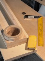
On my bench; AP555 analyzer, AP Acoustic software and calibrated GRAS microphones.
Indeed those are of major concern. In the Elsinores these are well sorted by a number of things, 1) the port is at the rear, 2) extremely large internal volume, 3) the diameter of the port is larger than its length and 4) the highly resistive nature of the internal volume, most of the mids are filtered out by the time it reaches the port.
A number of people have long had misgivings about vented enclosures and they have good reasons. But it just makes the design goals harder to achieve, but they can be achieved.
I have had a number of people converted, that a very well sorted (and rare) vented enclosure can be amazing and have its own advantages over sealed. One is that lowering excursion in a driver that handles the midrange, lowers critical high-order and FM-like distortions in the midrange. The Purifi drivers take this to almost extreme, but with the standard SB Acoustics drivers, this is still well achieved, like 1/4 the excursion required for a target SPL.
Another way to deal with these distortions is to add a series inductor to the driver that is at least equal to the driver inductance at 1KHz. This lowers excursion-dependant distortions even further. Many have not woken up to this yet.
As for bass quality, set up the Elsinores in a really good room and top equipment, and many will say "why do you need a subwoofer?"
BTW, nice equipment. My own goto mic is Earthworks M30 and it works with my 24V in my ClioFW01 and also with 48V with other equipment, so that choice was a no-brainer.
My late Dad going back a long time worked for B&K, and many still consider the standard in mics.
Joe:
I am struggling to find a couple of inductors for my Hamlet project (Jantzen's coils are not readily available). Madisound, a notable supplier in the US, offers a line of inexpensive 19 gauge inductors. Would they be suitable for L3 and L5, or do those positions demand something more substantial?
Many thanks,
Scott

I think I was looking at the wrong crossover, but this may be the correct one - https://www.diyaudio.com/community/threads/the-elsinore-project-thread.97043/post-6856313
L5 wants to be 0m055H with a resistance of 100mΩ. The Madisound appears to be OK there - https://www.madisoundspeakerstore.com/air-core-19-awg/madisound-0.1-mh-19-awg-air-core-inductor/
However, that is for the 0m1H for unwinding. The 0m05H shows as having a resistance of 170mΩ, which seems to be a mistake. In any case, it shouldn't matter and you can compensate the resistance by trading it against the resistor value.. as long as it doesn't cause heat issues in the inductor. Since this is the 4k5Hz circuit, and given the values, I suspect it will be fine.
Parts Express can get the actual parts secified in Joe's parts list but they will take between 9-15 weeks to arrive, are non-refundable and you can't cancel the order. They also have to look them up and get pricing for them first. I spoke to Beverly about this. She got me the pricing on the NRXC parts. If you are interested, PM me and I will share the numbers.Joe:
I am struggling to find a couple of inductors for my Hamlet project (Jantzen's coils are not readily available). Madisound, a notable supplier in the US, offers a line of inexpensive 19 gauge inductors. Would they be suitable for L3 and L5, or do those positions demand something more substantial?
Many thanks,
Scott
I spent some time talking to Chad at Meniscus about the parts needed. They found a bunch of substitutes that I am going to try to populate the black (smaller) PCB board with them. I will post how it works out here. I suspect I will need to mount a few parts onto the bottom of the PCB and use standoffs to mount it into the speaker cabinets. We shall see.
UPDATE:
There are some changes to the Crossover to take note. There was always a possibility that some tweak would be found, but the changes are small. Please note the components marked with a red Asterix. *

* R5: 33R (IMPORTANT). This is a new added component. As the ULD drivers have concave dustcap shaped cones, it has been noted that with a single inductor doing the filtering to the top two ULD drivers, this means that you get a bit more pronounced "BBC Dip" effect than the SB17 type drivers. This is about how we come out of it at frequencies above the dip. Adding R5 33R did a subtle but well worth improvement.
* R4 changed from 8R2 to 6R8
* C5 changed from 0.47uF to 0.22uF
These two values are adjusted to to match the effect of R5 on the electrical side. These are less important than adding the 33R resistor.
If you have already built the crossover, then just add 33R as that is the most important. If you are starting now, use the new values.
Let me know if the above is all clear.
There are some changes to the Crossover to take note. There was always a possibility that some tweak would be found, but the changes are small. Please note the components marked with a red Asterix. *
* R5: 33R (IMPORTANT). This is a new added component. As the ULD drivers have concave dustcap shaped cones, it has been noted that with a single inductor doing the filtering to the top two ULD drivers, this means that you get a bit more pronounced "BBC Dip" effect than the SB17 type drivers. This is about how we come out of it at frequencies above the dip. Adding R5 33R did a subtle but well worth improvement.
* R4 changed from 8R2 to 6R8
* C5 changed from 0.47uF to 0.22uF
These two values are adjusted to to match the effect of R5 on the electrical side. These are less important than adding the 33R resistor.
If you have already built the crossover, then just add 33R as that is the most important. If you are starting now, use the new values.
Let me know if the above is all clear.
Re 18mH Inductor:
This is clearly a tricky component as the ones usually available have thick gauge wire and low DC resistance. But in this instance it is better to use a higher gauge and this one below uses 24AWG and has 3.2 Ohm resistance, which is near perfect for our requirements and makes the inductor more compact. The resistor that is already in series with it makes it unnecessary to use low resistance inductor. Just reduce the value of the series resistor.
Note how reasonably priced (AUD$) and the dimensions.


https://speakerbug.com.au/index.php?route=product/product&path=18_45&product_id=967
I got in touch with www.speakerbug.com and asked if they could offer 30 from Jantzen, so this batch was made for us. I got 30 and Nigel at SpeakerBug also got 30.
This inductor and dimensions, this is what the PCB was designed for. This is the reason that I sell the PCB and the 18mH inductor together. I did that part to make it easier for you guys.
I had a speaker manufacturer friend over, he was already well acquainted with the Elsinores and their somewhat different but yet (according to him) 'scientific' based design philosophy behind them. He naturally wanted to hear the ULD version and came over for nearly five hours. He said that if they were to be commercially made he could not see them selling for less that $35.000 and likely a fair bit more. He rightly pointed out that there were speakers out there that looked the part, smartly finished and whilst the drivers were made to look impressive, they were all looks and actually not top notch drivers. Ain't that the truth!
This is clearly a tricky component as the ones usually available have thick gauge wire and low DC resistance. But in this instance it is better to use a higher gauge and this one below uses 24AWG and has 3.2 Ohm resistance, which is near perfect for our requirements and makes the inductor more compact. The resistor that is already in series with it makes it unnecessary to use low resistance inductor. Just reduce the value of the series resistor.
Note how reasonably priced (AUD$) and the dimensions.
https://speakerbug.com.au/index.php?route=product/product&path=18_45&product_id=967
I got in touch with www.speakerbug.com and asked if they could offer 30 from Jantzen, so this batch was made for us. I got 30 and Nigel at SpeakerBug also got 30.
This inductor and dimensions, this is what the PCB was designed for. This is the reason that I sell the PCB and the 18mH inductor together. I did that part to make it easier for you guys.
I had a speaker manufacturer friend over, he was already well acquainted with the Elsinores and their somewhat different but yet (according to him) 'scientific' based design philosophy behind them. He naturally wanted to hear the ULD version and came over for nearly five hours. He said that if they were to be commercially made he could not see them selling for less that $35.000 and likely a fair bit more. He rightly pointed out that there were speakers out there that looked the part, smartly finished and whilst the drivers were made to look impressive, they were all looks and actually not top notch drivers. Ain't that the truth!
This thread has progressed greatly since the last time I was tracking it. I have the Nomex 830875s and Peerless HDSs sitting from a decade ago when I was planning to do this build. What would be the best version box/x-over to build the Elsinores based on those drivers, considering everything learned to date? Mk5 design still the way to go? Would I be better off selling the 830875's off and building a newer version? I can comb through the thread, but figured that if there was an easy answer, I'd ask first.
Last edited:
I mentioned in post #4,791 that I would report back with the fitment of the parts from Meniscus. The inductors worked out well. I used two film 33uf caps rather than the bipolar electrolytic (I didn't feel like shopping around for parts and they only had the films.) and they did not fit on the top side of the board along with all of the other components so I just mounted them to the bottom. I also used Metal Oxide resistors which were slightly long but still manageable. If you sourced the Bipolar caps for C2 and C4 as well as went with the sand cast, everything would fit just perfectly without any hassle.
The big thing is that the inductors fit well enough.


The big thing is that the inductors fit well enough.
- Home
- Loudspeakers
- Multi-Way
- The "Elsinore Project" Thread