Although I've got no white smoke and nothing has catastrophically failed - YET. I'm loathe to keep power on this for too long for measurements.
I only build these, I don't design them so any pointers as to which area I should target first with the meter would be much appreciated.
I only build these, I don't design them so any pointers as to which area I should target first with the meter would be much appreciated.
OK I've taken some readings ?
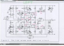
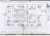
Now, if you recall, the LH amp seems OK and the RH amp is at fault.
To my novice brain I would suspect the op-amp.
On the working amp everything is stable and the ouput of the op-amp is a steady 0.19V.
On the faulty amp the output of the op-amp is unstable and seems to keep climbing to round the 3.5V mark. Differences in readings along a pcb trace are due to the voltages changing as I move the MM probe around.
Both PCBs are identical and the components are identical.
Attachments
Last edited:
Please check the voltage on the base of TR1 and TR3 for both channels and report the result ") edit: just noticed RichieBoy suggested replacing them.... based on the voltage differences you are seeing I'm suspicious of them... could also be a bad joint on R10 or R12 or possibly bad C11/C13.
edit: just noticed RichieBoy suggested replacing them.... based on the voltage differences you are seeing I'm suspicious of them... could also be a bad joint on R10 or R12 or possibly bad C11/C13.
Tony.
edit: just noticed RichieBoy suggested replacing them.... based on the voltage differences you are seeing I'm suspicious of them... could also be a bad joint on R10 or R12 or possibly bad C11/C13. Tony.
Last edited:
- Status
- This old topic is closed. If you want to reopen this topic, contact a moderator using the "Report Post" button.
- Home
- Amplifiers
- Solid State
- The David N.J.White 100W MOSFET amplifier