while you're in there measure the voltages at the base of tr1 (or across R10) and tr3 (or across R12) as well.
fwiw it were my amp i'd just snip the leads of TR4 and TR5 near the 90 degree bends i/o desoldering them off the pcb. Easy job to resolder them after. This also makes it easy to check that TR4,TR5 and TR2 are properly insulated from the heatsink. But your decision.
fwiw it were my amp i'd just snip the leads of TR4 and TR5 near the 90 degree bends i/o desoldering them off the pcb. Easy job to resolder them after. This also makes it easy to check that TR4,TR5 and TR2 are properly insulated from the heatsink. But your decision.
Last edited:
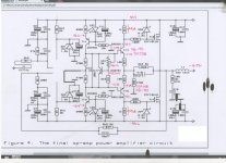
No mysteryThere is a definite problem with TR5, be it incorrect polarity device, a faulty device or an incorrectly fitted device. Whether there are other problems remains to be seen.
agree but it apparently tested out above ok ?
agree but it apparently tested out above ok ?
Not possible
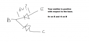
Its the same as saying "I have 6 volts across a forward biased silicon diode"... but it checks OK. There is one more possibility, but I would doubt this, and that is that the whole area around the transistor is oscillating at RF which would make all DC readings invalid. One quick check with a scope would prove/disprove that though... as would a well placed finger around that area.
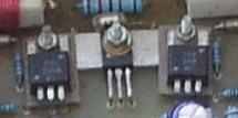
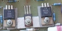
are you sure they are installed the same way on both channels. Look at the middle transistor in each of these images carefully.
edit: also shouldn't there be an insulator?
Tony.
edit: also shouldn't there be an insulator?
Tony.
Attachments
Last edited:
I've just done diode tests on both TR4 and TR5 and they both measure about 0.9V BE and BC.
Try measuring the voltage across the B-E junction of TR5 in the amplifier and confirm that the 0v and -6v results you obtained previously translate into a measure 6 volts across the junction.
- Status
- This old topic is closed. If you want to reopen this topic, contact a moderator using the "Report Post" button.
- Home
- Amplifiers
- Solid State
- The David N.J.White 100W MOSFET amplifier