This is an old project that I never got around to finishing, the PCB's have been lying around for donkeys years. I do remember testing them individually and setting the bias but they never saw action as a stereo pair.
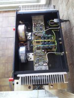
Now, they have been built into a Dual Mono pair. As the transformers were bought at different times their characteristics are slightly different. Although both nominally 35-0-35 at 250VA, the DC voltage to the two amps is slightly different. One has 50-0-50 and the other 53-0-53.
AFAIK this will not affect them in any way other than the fact that one will clip slightly earlier than the other.
Attachments
Interesting ... Looks like a classic cottage industry britamp from the 80's - any selling points from the designer on this one ?
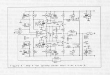
It is based on the original Hitachi Lateral FET data sheet. JLH implemented it in his 80W MOS-FET amplifier as did Maplin with their 150W MOSFET amplifier.
I beleive this comes from about the early 90s.
It's still a very competent amplifier that will beat most commercial offerings hands down.
It's nothing like the Hitachi data book circuit, it uses an op-amp as input stage and providing most of the voltage gain then the output stage provides a low amount of gain to boost the limited swing from the op-amp.
In practice, no, you won't see any difference in performance with the rail difference betwen channels and your assumption is correct.
As a building standards comment, it looks good but green/yellow coloured wire is reserved for safety earth connections only. Also you should insulate your switch terminals.
It looks like the amplifier ground is not connected to safety earth, I think you had some ground loop problems on another thread, but it's worth trying to get right for safety reasons.
Ok so I don't think the power rail differences are going to matter much.
There's something quite interesting about the amplifier schematic tho that's not so run of the mill..... For starters the op stage is not operated as a follower (output is taken from the drains) which is a stark contrast to the datasheet amps but there is localized feedback and loop feedback. The way the op stage is biased is also interesting ....
If you have the article would be worth a post IMO.....
The PDF article found after a casual search on the forum:
http://www.diyaudio.com/forums/solid-state/242014-anyone-recognise-these.html#post3621440
http://www.diyaudio.com/forums/solid-state/242014-anyone-recognise-these.html#post3621440
This is the other schematic http://www.diyaudio.com/forums/soli...-ab-125w-mosfet-amp-schematic-discussion.html
how to increase the power into 250 watt?
best regards,
josh
how to increase the power into 250 watt?
best regards,
josh
Is this a clue or a Red Herring ?
I can't find anything immediately wrong.
The amplifier bias was adjusted when the amps were initially built.
However, the faulty amp now has bias of only 30mA as opposed to 100mA. The bias does adjust but requires almost the full travel of VR1 to achieve 100mA.
OK the supply is very slightly different. The LH amp is using the original 50-0-50V PSU that used to power both amps, the RH amp now has its own 250VA 53-0-53V supply.
I'm aware that germanium transistors used to age, but I though that didn't happen with silicon?
- Status
- This old topic is closed. If you want to reopen this topic, contact a moderator using the "Report Post" button.
- Home
- Amplifiers
- Solid State
- The David N.J.White 100W MOSFET amplifier