Both new inputs could be implemented in the official "QUAD" amp. ;-)
Oops! What happened with that 10R?
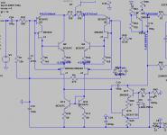
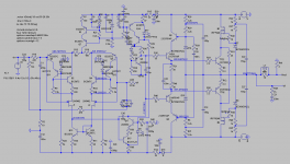
And violá, the "QUAD" with "bootstrapped cascoded-CFP input" .
While we wait for the big fight...
Attachments
Hi Max,And the "Bootsrapped Bootstrapped-CFP input" version.
Both new input could be implemented in the official "QUAD" amp. ;-)
I took a short look at the CFP design in #320, but found that Q14 was just a generic transistor !!
When replacing the first four drivers by BD139/BD140, I got nothing but oscillation.
When also replacing the second set of four, oscillations continued.
I'm not so fond of this type of output stage, just because the difficulty to get it stable.
First try to get a working model with exactly the transistors you are going to use, not doing that is a waste of time.
Hans
Oops! My bad. Sorry.
Your completelly right! The addition of the driver completelly unbalanced it. No one is stable.
But without driver, meaning bootstrapped cascoded-CFP input and ouput seems stable.
Do you think that omiting the driver to a Darlington (or a Sziklai) bootstrapped will be too much for the VAS?
Simulations show them stable...
Last edited:
Guys, forget all the circuits that say "driver" or "drivertest".
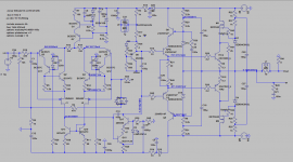
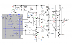
This one seems stable.
The "QUAD" with bootstrapped cascoded-CFP input is also stable in simulation.
This one seems stable.
The "QUAD" with bootstrapped cascoded-CFP input is also stable in simulation.
Attachments
Last edited:
Not as stable as you think, I'll come back to it tomorrow to show you why.Guys, forget all the circuits that say "driver" or "drivertest".
This one seems stable.
The "QUAD" with bootstrapped cascoded-CFP input is also stable in simulation.
Maybe you can explain in the meantime why you have made the input more complex.
Hans
Not as stable as you think, I'll come back to it tomorrow to show you why.
Maybe you can explain in the meantime why you have made the input more complex.
Hans
Dear Hans,
The added complexity of the input will be evaluated in sonic terms.
As with all my experiments--> stability--> sonics...to simplify the process.
I mean, we see mods being evaluated by its effect on THD, IMD, BW, etc but seldom evaluated also for its sonic performance...
This cascode-inside-a-CFP was one of Hepäistos outputs...a nightmare to stabilize but good sounding.
Cheers,
M.
Dear Max,Dear Hans,
The added complexity of the input will be evaluated in sonic terms.
As with all my experiments--> stability--> sonics...to simplify the process.
I mean, we see mods being evaluated by its effect on THD, IMD, BW, etc but seldom evaluated also for its sonic performance...
This cascode-inside-a-CFP was one of Hepäistos outputs...a nightmare to stabilize but good sounding.
Cheers,
M.
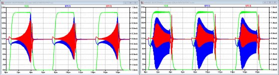
As promised I show you my findings.
I have made 2 models, the one you have sent me and a version with the BD139/BD140 that you have envisaged but for some reason not yet using in your Sim Model.
In both I have set the current through the output drivers to the same 129mA.
Now looking at the output square wave, it almost looks in your version at the left as if the output is stable.
But when magnifying the signal shows that there are oscillations visible at ca 20Mhz.
Now looking at the current through R52 and R53, you get a much better vision on these oscillations.
The image on the right is with the BD139/BD140 and is even worse.
To magnify the effect somewhat, I have reduced the Miller cap to 50pF and the input filter to 220 Ohm/220pF.
These oscillations are internal oscillations because of the CFP drivers.
You still need some modding to get rid of this.
To compare: with the drivers as emitter followers, I could easily reduce the Miller cap to 15pF without any problem.
At the end I fully agree that listening test are the final tests, but when something is oscillating you are not yet ready for listening tests.
Hans
Attachments
Dear Hans,
You are talking about the "bootstrapped cascoded-CFP INPUT and OUPUT" version, right?
Yes, I know the CFP outputs (even the simple version) are a nightmare to stabilize, even in the case that all appears OK on simulation, due to parasitics, probably. So, when I'll find the time and energy to deal with them again, I will start with a fresh new PCB and be prepared to add a cap or resistor here and there... for example, I've seen some commercial amps with b-cCaps at the drivers, though this never worked for me.
Yesterday, I made the "bootstrapped cascoded-CFP" input mod by adding a second BC556 to the CFP (or internal cascode as I call it) with reference to ground as my last schematic shows. I did not add a capacitor yet as it seems to work OK without it. Is it necessary?
I forgot to mention that this mod is discussed in Dr. Kolinummi's book, page n°140, with simulated THD comparison to other variations. He references the base to the main emitter through a 2V voltage source, though this did not work for me, perhaps I am using to much base current...
Preliminary listening test are positive.
I will elaborate this later if extended listening tests confirm findings.
Thank you, thank you very much for your revision and stimulation
M.
You are talking about the "bootstrapped cascoded-CFP INPUT and OUPUT" version, right?
Yes, I know the CFP outputs (even the simple version) are a nightmare to stabilize, even in the case that all appears OK on simulation, due to parasitics, probably. So, when I'll find the time and energy to deal with them again, I will start with a fresh new PCB and be prepared to add a cap or resistor here and there...
for example, I've seen some commercial amps with b-cCaps at the drivers, though this never worked for me. Yesterday, I made the "bootstrapped cascoded-CFP" input mod by adding a second BC556 to the CFP (or internal cascode as I call it) with reference to ground as my last schematic shows. I did not add a capacitor yet as it seems to work OK without it. Is it necessary?
I forgot to mention that this mod is discussed in Dr. Kolinummi's book, page n°140, with simulated THD comparison to other variations. He references the base to the main emitter through a 2V voltage source, though this did not work for me, perhaps I am using to much base current...
Preliminary listening test are positive.
I will elaborate this later if extended listening tests confirm findings.
Thank you, thank you very much for your revision and stimulation
M.
OK.
Guys, the cascode-inside-the-CFP is the best sounding input section so far and by far.
Now, I have not tested the JFET option (fewer parts but costly), only the BJT solution (more parts but cheaper) and I like better the sound with 3 diodes to ground (instead of two), but I will have to definitely test the JFET option on my TOKIN VFET amp, which uses a compound CFP input (JFET-->BJT) instead.
Thanks that I lacked the complementary IRFP9240 MOSFET, I get used to the sound of the amp with the other one, a 5210 if I remember correctly, on both my Amnesis amps. When I finally decide to mod them, the sound became more dynamic, rounder and bigger, with longer decays, but fuzzier. That fuzziness did not totally disappear after burning.in (48hrs minimum) but made the sound warmer, best suited for cold and detailed sources and speakers.
Which takes us to our initial working hypothesis, whose rationale (briefly) is as follows:
------------------------------------------------------------------------------------------------------------------------------------
*A perfectly THD scoring 3 stage amplifier fails to deliver in terms of musical bliss.
*There must be other parameters which influence the sound quality or some limiting step is being neglected.
*There is a theory that says that Thermal Memory affects transistor function and the proponents of that theory insist that the circuits with putative LTMD sound very "musical", though it will be difficult to discern if the possible effects are due to LTMD or to other effects, due that the said circuits will probably be more linear...etc.
*Once the said circuits, which belong to the input and VAS stages, are working, who knows if the output section will be at the level of them...
*Test with alternative output sections will have to be done to see if now the common EF output section is a limiting step.
*Once the output section has been optimized other limiting steps could present themselves.
*There could be a never ending cycle of experimentation with incremental gains in sound Q.
------------------------------------------------------------------------------------------------------------------------------------
I believe that the addition of the complementary MOSFET cascodes made evident that previous sections are limiting the sound Q. My bootstrapped cascode-CFP input mod now is on par to the rest of the amp , though I always suspect the VAS as being the most difficult section.
If someone knows a better way to implement the internal cascode of the PNP BJTs, please share.
Best wishes to all my fellow DIYers,
M.
Guys, the cascode-inside-the-CFP is the best sounding input section so far and by far.
Now, I have not tested the JFET option (fewer parts but costly), only the BJT solution (more parts but cheaper) and I like better the sound with 3 diodes to ground (instead of two), but I will have to definitely test the JFET option on my TOKIN VFET amp, which uses a compound CFP input (JFET-->BJT) instead.
Thanks that I lacked the complementary IRFP9240 MOSFET, I get used to the sound of the amp with the other one, a 5210 if I remember correctly, on both my Amnesis amps. When I finally decide to mod them, the sound became more dynamic, rounder and bigger, with longer decays, but fuzzier. That fuzziness did not totally disappear after burning.in (48hrs minimum) but made the sound warmer, best suited for cold and detailed sources and speakers.
Which takes us to our initial working hypothesis, whose rationale (briefly) is as follows:
------------------------------------------------------------------------------------------------------------------------------------
*A perfectly THD scoring 3 stage amplifier fails to deliver in terms of musical bliss.
*There must be other parameters which influence the sound quality or some limiting step is being neglected.
*There is a theory that says that Thermal Memory affects transistor function and the proponents of that theory insist that the circuits with putative LTMD sound very "musical", though it will be difficult to discern if the possible effects are due to LTMD or to other effects, due that the said circuits will probably be more linear...etc.
*Once the said circuits, which belong to the input and VAS stages, are working, who knows if the output section will be at the level of them...
*Test with alternative output sections will have to be done to see if now the common EF output section is a limiting step.
*Once the output section has been optimized other limiting steps could present themselves.
*There could be a never ending cycle of experimentation
with incremental gains in sound Q.------------------------------------------------------------------------------------------------------------------------------------
I believe that the addition of the complementary MOSFET cascodes made evident that previous sections are limiting the sound Q. My bootstrapped cascode-CFP input mod now is on par to the rest of the amp
, though I always suspect the VAS as being the most difficult section. If someone knows a better way to implement the internal cascode of the PNP BJTs, please share.
Best wishes to all my fellow DIYers,
M.

Hi Max,
I watched the latest findings and wondered about the consequences/changes
for an update of my present preliminary layout.
I already started an update based on your new official Amnesis QUAD bootstrapp schematics (post #331) and Triple Bootstrap (post #332) incl. new input stage.
Is the CCS VAS still an option for layout or do you recommend the Bootstrapped VAS only (sound, stability)
Is the cascoded Sziklai output (post#324) an option that should be considered for layout update (a combi layout acc. to posts #331 and #324 is possible).
Due to the increasing number of small signal diodes (up to 14) I want to replace the present type 1N4148 by the SMD type BAS16J to keep traces short.
Any objections?
Cheers
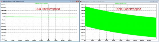
Hi Max,And for those who do not like complications, the "TRIPLE" bootstrapped.
This is the definitive prove that thermal modulation has nothing to do with the experienced sound.
I did the same test as before , for the dual bootstrapped CFP below at the left and for the new triple bootstrapped input configuration at the right, both on the same scale.
See what a huge difference it makes in heating up between the two.
Hans
Attachments
Hi Max,
I already started an update based on your new official Amnesis QUAD bootstrapp schematics (post #331) and Triple Bootstrap (post #332) incl. new input stage.
Dear JOSI1,
It would be great to have those PCBs to experiment further. While the "TRIPLE" (post #332) is attractive and simulates well, it is not tested yet. Besides, we don't know how much interest it will have...
The "QUAD" should allow for every variation possible, and more,
though at the expense of longer vias...Is the CCS VAS still an option for layout or do you recommend the Bootstrapped VAS only (sound, stability)
Again, though a nice addition, the CCS-VAS version would have to be checked for to stability and sound before recommending
I attach a version...Is the cascoded Sziklai output (post#324) an option that should be considered for layout update (a combi layout acc. to posts #331 and #324 is possible).
The Sziklai is potentially problematic and at this stage I will consider it for further experimentation only. Even the more tested "QUAD" has a great chance of causing some troubles, that is why I recommend we stick to the proven one. This is not a project for beginners, like yours truly
, or for the faint of hart. A resilient spirit will be needed when the thing start to oscillate Due to the increasing number of small signal diodes (up to 14) I want to replace the present type 1N4148 by the SMD type BAS16J to keep traces short.
Any objections?
Cheers
OK. The only ones that need to be axial are those on the power supply lines to allow for higher current and eventually to serve for independent power to the input-VAS.
As long as we get the needed -1.4V to -2V referenced to ground.I will have to buy those then.
Hi Max,
This is the definitive prove that thermal modulation has nothing to do with the experienced sound.
I did the same test as before , for the dual bootstrapped CFP below at the left and for the new triple bootstrapped input configuration at the right, both on the same scale.
See what a huge difference it makes in heating up between the two.
Hans
Dear Hans, this is very interesting but please remind us which schematics and where you measure as I'm also confused sometimes with so many iterations of the amp and we need to settle this issue. A more detailed explanation of your findings is needed.
This whole set of experiments will, hopefully, give us better sounding though complex (input) circuits, and I am not in the least preocupied if it is due to LTMD or THD or TIM or whatever. We live to learn...
As I said before, the transistors seem to be gregarious beings that like to share the burden of the task between pairs Cheers,
M.
Attachments
Last edited:
Dear Max,Dear Hans, this is very interesting but please remind us which schematics and where you measure as I'm also confused sometimes with so many iterations of the amp and we need to settle this issue. A more detailed explanation of your findings is needed.
This whole set of experiments will, hopefully, give us better sounding though complex (input) circuits, and I am not in the least preocupied if it is due to LTMD or THD or TIM or whatever. We live to learn...
Cheers,
M.
The power measurements I made were as before:
Vce(Q3)*Ic(Q3)=Pwr(Q3) while driven from a 1Khz 0.7 Volt sinus wave.
Pwr(Q3) then was processed by a LP filter with a 0.5sec time constant for simulating the thermal transient of a SOT23 transistor.
The plots, being the 1Khz Signal caused Power change minus the steady state DC Power value, is what you see.
Then I paid some more interest in the input configs that you used.
And again, I hit large differences with the presented tables in Kolumnis book on page 140/141.
I used a differential input pair isolated from Vas and Output stage, and connected a 100K load one side to -22Volt and the other side to Collector Q13.
I gave a 16mV eff input signal causing the required 10V eff on the 100K resistor, just as Kolumni did. This calculated with into a gm of (10V/(16mV*100K) = 6.3 mA/V.
Distortion was measured between your double and triple bootstrapped input versions.
They were both exactly the same, but very much higher as in the book, meaning that he probably used a much lower output voltage !
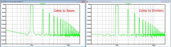
However, when changing the connection from J1 and J2's gate to the lower side of R13/R14, the higher harmonics went down a bit, again exactly the same for both models.
Look at 5Khz, the 5th harmonic went down by a factor 10 or 20dB.
In your listening tests it might be good to include this option.
See the image below for the two different gate connections.
At last, I tried to modify your triple bootstrapped version just as in Fig 5.28b in the book, as well with Q4 as a Fet and with a transistor.
I also tried with ideal voltage and current sources, but never got the combination stable, again raising my doubts whether this combination was ever tried in this form.
Hans
Attachments
Last edited:
Dear Hans,
This is great work and a big effort from your part. I congratulate you.
Now I have to digest all this info.
The thing that troubles me is that you used a circuit that says "buffer" on the title: that refers to my experiments with the good sounding but bad measuring "PNP common-base buffer" to the differential pair output. The one that behaved poorly on the square wave test due, not to oscillation, but to poor slew-rate.
If you have the time, please post proposed changes to the circuit for us to evaluate.
BTW, as you are technically proficient, unlike me, what would be the power expected from the +/-34V swing into 8ohm?
Yeah, I know and you know that I'm lazy.
Oops! The "empanadas" arrived, sorry.
M.
I'm not so sure what you mean with "buffer" on the title.Dear Hans,
This is great work and a big effort from your part. I congratulate you.
Now I have to digest all this info.
The thing that troubles me is that you used a circuit that says "buffer" on the title: that refers to my experiments with the good sounding but bad measuring "PNP common-base buffer" to the differential pair output. The one that behaved poorly on the square wave test due, not to oscillation, but to poor slew-rate.
If you have the time, please post proposed changes to the circuit for us to evaluate.
BTW, as you are technically proficient, unlike me, what would be the power expected from the +/-34V swing into 8ohm?
Yeah, I know and you know that I'm lazy.
Oops! The "empanadas" arrived, sorry.
M.
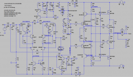
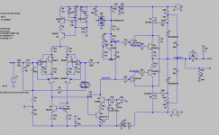
To show you what I did, have a look at the two versions of your triple bootstrapped input circuit in the .asc file below.
Difference is the connection of the two gates.
Output is 10Veff@1Khz on a 100K resistor, like Kolinummi did.
With yout dual bootstrapped version I did exactly the same.
To know the power to be produced into your 8 Ohm load, the Mosfet takes 4 volt from your output swing, giving 34 - 4 = Vpeak of 30Volt or 21 Veff.
Output pwr will be V^2/R=55 Watt.
For 44Volt supply it would be exactly 100 Watt.
Hans
Attachments
I'm not so sure what you mean with "buffer" on the title.
To show you what I did, have a look at the two versions of your triple bootstrapped input circuit in the .asc file below.
Difference is the connection of the two gates.
Output is 10Veff@1Khz on a 100K resistor, like Kolinummi did.
Ah! very interesting. I tried to connect that way the second cascoded BJT but it cannot be done. Is it right to have a voltage output instead of a current output? Can they be compared?
Unfortunatelly, when I tried the gate-to-emitter mod on the "QUAD" the stability margin decreased and the THD deteriorated several orders of magnitude...
Anyway, isn't the whole arrangement (bootstrapped cascoded-CFP) susceptible to thermal analysis? Can you see what happens to the JFET?
As I understand, it is not the absolute value of thermal production but the alteration of it following the non constant musical signal. Maybe non-periodic bursts of square waves could show something useful...
Hephaïstos measured single wave effects on Vbe, if I remember correctly...I will try to find the articles...can you plot Vbe v/s time?
To know the power to be produced into your 8 Ohm load, the Mosfet takes 4 volt from your output swing, giving 34 - 4 = Vpeak of 30Volt or 21 Veff.
Output pwr will be V^2/R=55 Watt.
For 44Volt supply it would be exactly 100 Watt.
Hans
Thanks. That was the formula that I was looking for. That is V(RMS) squared, divide by the impedance. I already had substracted the limits of the bootstrapp. When one alters the resistor's ratio +/-39V can be extracted from the +/-44 supplies before clipping. Usually, I would consider +/-35 safe output with 1K/1K-> 72W.
My present amps could output +/-24V swing, hence 36W. Did I got it right?
To be perfectly responsible to the hypothetical public following the conversation, today I tried the Bootstrapped Darlington output which may appeal the more simplicity-inclined DIYers...
It works, but with the 10/15 Ohm stopper gate resistors for the MOSFETs it oscillated beautifully at +/-12.5MHz, so in my despair, I increased R43 (N channel stooper) to 330R and that stopped the overt oscillation. I may have to increase also the other one for a small tendency to widen the scope line at negative power peaks...and also the perfect (lowest) value must be explored.
How does it sound on first minutes? all-rigth, but I would say a bit less dynamic, especially noticeable on midrange and HF, less focused. It could be a "burning-in" problem. I will update this. You see, with my Amnesis QUAD the sound must jump out the speakers. Once you get used to this, you detect
the lack of it easily...
Cheers,
M.
which may appeal the more simplicity-inclined DIYers...It works, but with the 10/15 Ohm stopper gate resistors for the MOSFETs it oscillated beautifully at +/-12.5MHz, so in my despair, I increased R43 (N channel stooper) to 330R and that stopped the overt oscillation. I may have to increase also the other one for a small tendency to widen the scope line at negative power peaks...and also the perfect (lowest) value must be explored.
How does it sound on first minutes? all-rigth, but I would say a bit less dynamic, especially noticeable on midrange and HF, less focused. It could be a "burning-in" problem. I will update this. You see, with my Amnesis QUAD the sound must jump out the speakers. Once you get used to this, you detect
the lack of it easily...
Cheers,
M.
Attachments
Last edited:
- Home
- Amplifiers
- Solid State
- The AMNESIS amp: a good amplifier, like a gentleman, has no memory.