Dear Hans wrote:
Great!!!
That could be the thing to optimization.
Thanks god it is Sun-day.
In the other Amnesis (linear PS; no oscillation), in which I made the 2K source to source (or better, collector to collector, as it is nearer) mod yesterday, has a 20K pot making the bias fort the VAS cascode. That one can also be reduced then...
Dear Symon wrote:
I just happened to have a bunch of these canned transistors. Cascodying/bootstrapping them (or any output BJT) seems to improve the sound of the output section a lot. Anyway, every one is adviced to try the simple EF output then the cascoded one, step by step, and judge for yourselves if I am drunk or what...
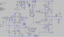
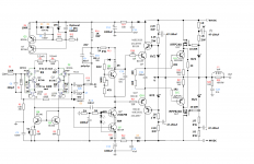
The "white schematics" are the "official". There is no final "official" yet. As I explained, I don't have the models for the BD139/140 and 2Sc47XX/2SA1837 drivers, so that makes up for the difference in parts.
The "official" outputs are 5200/1943 and its MOSFET are indedd 240/9240 as is correctly depicted in the .asc file.
Dear JOSI1,
Yes, those are the ones. Though any good medium power BJT would do.
Yesterday I tortured the amp with Bartok's double piano concerto, which has tremendous dynamic contrasts. In one sustained ffff, much louder than I use to, the same BD139 driver's cascode that I fried before with the emitter follower VAS, began to output smoke, while still producing music. I was too slow to power down and it was shorted. Perhaps it was not well tied to heat-sink...I did not see oscillations (focused on the part smoking) but I installed stopper gate resistor of 10R in the positive MOSFET, just in case. Amp works great after the replacement, even with lesser torture...
A 10 to 20R gate resistor won't do much harm, will it?
I am having fun again.
Big thanks to all of you,
M.
Dear Max,
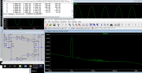
I just found a last thing for you to change.
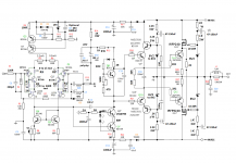
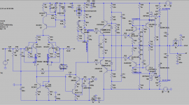
R35 and R47 are now 10K each. This is too much to supply Q17 with enough base current.
See image below for the difference it makes when changing these values to resp 3k3 and 1K.
Great!!!
That could be the thing to optimization.
Thanks god it is Sun-day.
In the other Amnesis (linear PS; no oscillation), in which I made the 2K source to source (or better, collector to collector, as it is nearer) mod yesterday, has a 20K pot making the bias fort the VAS cascode. That one can also be reduced then...
Dear Symon wrote:
Hi Max,
I noticed in the pictures of your prototype that the output transistors are MJ15023 and MJ15024 which are much slower and are less linear than the devices in the simulation. Also the Drivers in the prototype are TO126 types BD139 / BD140? not the fast SMD devices in the simulation.
I wonder if the reason you head a difference with Cascoded output is just improving the performance of devices in the prototype, and may not be required with the actual sustained Beta devices specified in the simulation.
Might be useful to list all the devices in the prototype so a more accurate simulation can be built.
Regards,
Symon
I just happened to have a bunch of these canned transistors. Cascodying/bootstrapping them (or any output BJT) seems to improve the sound of the output section a lot. Anyway, every one is adviced to try the simple EF output then the cascoded one, step by step, and judge for yourselves if I am drunk or what...
The "white schematics" are the "official". There is no final "official" yet. As I explained, I don't have the models for the BD139/140 and 2Sc47XX/2SA1837 drivers, so that makes up for the difference in parts.
The "official" outputs are 5200/1943 and its MOSFET are indedd 240/9240 as is correctly depicted in the .asc file.
Dear JOSI1,
Yes, those are the ones. Though any good medium power BJT would do.
Yesterday I tortured the amp with Bartok's double piano concerto, which has tremendous dynamic contrasts. In one sustained ffff, much louder than I use to, the same BD139 driver's cascode that I fried before with the emitter follower VAS, began to output smoke, while still producing music. I was too slow to power down and it was shorted. Perhaps it was not well tied to heat-sink...I did not see oscillations (focused on the part smoking) but I installed stopper gate resistor of 10R in the positive MOSFET, just in case. Amp works great after the replacement, even with lesser torture...
A 10 to 20R gate resistor won't do much harm, will it?
I am having fun again.
Big thanks to all of you,
M.
Listening tests are going well with the new 3K3/1K mod for the VAS cascode.
Maybe it's time to re-visit some old ideas, like Pass' style EF/Darlington output, for those who like simpler solutions.
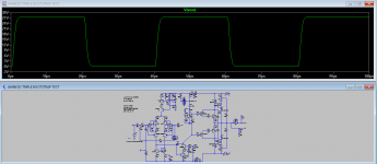
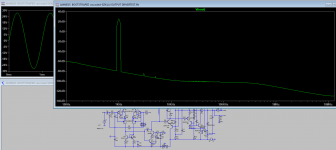
Edit: apparently R21, R48 and C20 are not needed. THD 0.000763% with 2nd harmonic predominant.
Edit n°2: stability margins are not brilliant but square wave test looks good.
Also, the common bias for driver and output is feasible and can be tested.
Cheers,
M.
PS: I am a big fan of Van Der Graaf Generator, so I'm including them for my tests.
Maybe it's time to re-visit some old ideas, like Pass' style EF/Darlington output, for those who like simpler solutions.
Edit: apparently R21, R48 and C20 are not needed. THD 0.000763% with 2nd harmonic predominant.
Edit n°2: stability margins are not brilliant but square wave test looks good.
Also, the common bias for driver and output is feasible and can be tested.
Cheers,
M.
PS: I am a big fan of Van Der Graaf Generator, so I'm including them for my tests.
Attachments
Last edited:
That cascoded Darlington output from Nelson Pass is interesting isn't it.
Remember one can increase headroom (going nearer PS voltage) by making the biasing resistors for the Vref asymetric.
Dear Hans wrote,
Funny that you mention it. Now that we found the origin of the oscillation bursts, we can go back to the looser original input filter: 220R + 220pF, which gives good numbers.
I thought safety margins were much stringent...
Disclaimer: all R and C values are subject to change without previous warning
Cheers,
M.
Remember one can increase headroom (going nearer PS voltage) by making the biasing resistors for the Vref asymetric.
Dear Hans wrote,
With a Miller cap of 100pF and the filter at the input of your amp, Slew Rate at the output is now 25V/usec and with a 50pF Miller cap it is 35V/usec.
Both values are very good.
Funny that you mention it. Now that we found the origin of the oscillation bursts, we can go back to the looser original input filter: 220R + 220pF, which gives good numbers.
I thought safety margins were much stringent...
Disclaimer: all R and C values are subject to change without previous warning
Cheers,
M.
Attachments
Hi Max,
interresting new version, I tried running it but substitued model from Bob Cordells libary for more representative devices. I used BD139/BD140 for the drivers, and MJ21193/4 for the output devices. Manly because these are closer to the characteristics of the devices you are actually using than the 2SC5200 etc.
The one thing I will note is you need to adjust the bias generator, standing current is currently over 500mA. So operating in Class A up to about 14V peak output.
Becareful with this CFP output's tend to oscilate, especially if the driver doesn't hae low Cob value.
That said, would be interesting to hear how well the actual circuit works.
Regards
Symon
Yes, I know CFP do oscillate. When I began I tried the most strange outputs you can imagine. The more complex, the more unstable and good sounding they were
Edit: I am now playing with the resistor arrangment for tha Sziklai and THD is going down...
Of course, bias is set with a pot until desired current.
Glad you have the 139/140 models. Mind to share?
You know I am a nullity with LT-spice but maybe I can add them.
Be aware that the final prototype will use 5200/1943 as outputs, just for the abundance of them. Anyway, experimentation with different units is encouraged.
I am trying now to set a "bootstrapped cascoded-Sziklai" but it is tricky...
What do you think about that Bootstrapped-Darlington output?
Chhers,
M.
Attachments
Last edited:
Hi Max,
I used the model from Bob Cordell's web site
CordellAudio.com - SPICE Models
The reason I chose MJ21193/4 was because these are 4MHz devices like the MJ15023/4 that you are using in prototype. 2SC5200/2SA1943 are 30MHz so nearly 10 times faster.
So just trying to get closer to the circuit you built.
Regards,
Symon
Here is a new Amnesis.Lib including the BD139 and BD140.
Hans
Thanks, I will do my best.
The reason I chose MJ21193/4 was because these are 4MHz devices like the MJ15023/4 that you are using in prototype. 2SC5200/2SA1943 are 30MHz so nearly 10 times faster.
I got that. Do you see the effect of bootstrapping/cascodying? On BW or else.
My Red PCB Amnesis (Modded Blame ST from DestroyerX) does use 5200/1943. That one uses a linear supply with "charge-transfer", so I cannot say if the difference in sound comes from the different output units or not.
Thanks for the models. I will try to figure it out.
The bootstrapped Sziklai output with 1R emitter resistors needs further increase in Vbe multiplier resistor to control bias current. I wonder too what it sounds like.
My QUAD BOOTSTRAPPED (with SMPS) is on its third day of listening test, running stable and the sound is "very decent". The objective of the thread was to make an amp that was satisfactory to listen to classical music and for that transparency and dynamics were the ultimate goals. In that sense, this version is satisfactory. It has an open and detailed sound with lots of dynamic contrasts, remaining relaxed. I suspect it can be perfected, as everything, but it is fine like it is.
A "QUAD" PCB will allow for stepped experimentation on outputs: first, simple EF; second
bootstrapped output with simple driver; then bootstrapped Darlington; then perhaps bootstrapped Sziklai; then "QUAD"
Lots of fun. Maybe I can even perfect other more complex outputs...and finally the VFET bootstrapped output. Choose your flavor.
Cheers,
M.
Cheers,
M.
Hi Max
I found that the Output Cascode seemed to improve HF performance, using the slower devices. I suspect you will find the difference is much smaller with the faster more linear 2SC5200/1943 devices.
Note that in your favorite book, they only Cascode /Bootstrap the drivers, and this is mainly to reduce loading on the VAS.
But the ultimate goal is what it sounds like, so needs experiment
Watching with interest,
Symon
The reason I chose MJ21193/4 was because these are 4MHz devices like the MJ15023/4 that you are using in prototype. 2SC5200/2SA1943 are 30MHz so nearly 10 times faster.
I got that. Do you see the effect of bootstrapping/cascodying? On BW or else.
My Red PCB Amnesis (Modded Blame ST from DestroyerX) does use 5200/1943.
I found that the Output Cascode seemed to improve HF performance, using the slower devices. I suspect you will find the difference is much smaller with the faster more linear 2SC5200/1943 devices.
Note that in your favorite book, they only Cascode /Bootstrap the drivers, and this is mainly to reduce loading on the VAS.
But the ultimate goal is what it sounds like, so needs experiment
Watching with interest,
Symon
Hi Max
I found that the Output Cascode seemed to improve HF performance, using the slower devices. I suspect you will find the difference is much smaller with the faster more linear 2SC5200/1943 devices.
Note that in your favorite book, they only Cascode /Bootstrap the drivers, and this is mainly to reduce loading on the VAS.
But the ultimate goal is what it sounds like, so needs experiment
Watching with interest,
Symon
OK. That's what I imagined. Thanks.
Can you post some pics about the performance?
I am too busy and too lazy to study the hows and wheres of including .models at this moment, and also because previous attempts led to frustration
Today I will install IRFP9240 on the red PCB Amnesis, to be on symmetry.
Thanks for your interest and invaluable help.
M.
Dear Max,
What is the function of R3, 10 Ohm.
It is doing no harm, but why ?
Further everything seems O.K., in LTSpice it is still stable with a Miller cap of 15p.
Hans
Hi Hans,
I understand that that one isolates signal ground from power ground and reduces the risk of hum...
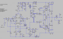
I still play with new outputs
Look at my bootstrapped cascoded-Sziklai output.
I may add a predriver like I've done long ago...
Cheers,
M.
Attachments
Hi Hans,
I understand that that one isolates signal ground from power ground and reduces the risk of hum...
I still play with new outputs
Look at my bootstrapped cascoded-Sziklai output.
I may add a predriver like I've done long ago...
Cheers,
M.
Hi Max,
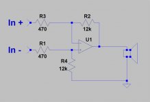
If you want to safeguard your amp against hum and ground loops, the image below gives the optimal layout.
Minus side of R4 has to be physically connected very close to the Speakers minus output, this point of course also connected to the signal ground or ground plane of the PCB as it is now.
The input signal does not have to be differential, it can just be the SE connection you are using now.
Hans
Attachments
Hi Max,
If you want to safeguard your amp against hum and ground loops, the image below gives the optimal layout.
Minus side of R4 has to be physically connected very close to the Speakers minus output, this point of course also connected to the signal ground or ground plane of the PCB as it is now.
The input signal does not have to be differential, it can just be the SE connection you are using now.
Hans
Thanks for that!
The amps are silent so far. It might be useful for my other amps, though.
I forgot an RC connection on the "QUAD BOOTSTRAP" schematic. Re-uploaded.
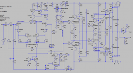
There goes also a "Bootstrapped Cascoded-CFP output with Driver"
version. Very tricky: a little change in Vbe circuit can make the current JUMP!
I will be trying another modded input section, probably.
Cheers,
M.
Attachments
Last edited:
Hi Hans,
connecting signal ground to noisey power ground via a small resistance is a standard way to to break hum loops. It's covered in Bob Cordells book chapter 18. It's not really new idea, I've seen it done in several circuits dating back to 1980's.
What you propose is closer to balanced input, which might be useful if the Pre amplifier is a long way from the Power Amplifer. It's more common on pre ampliers with multiple inputs. In this case the ground loop is most likely between the Power Amplifier and Pre-Amplifier.
Regards,
Symon
Hi Symon,Hi Hans,
connecting signal ground to noisey power ground via a small resistance is a standard way to to break hum loops. It's covered in Bob Cordells book chapter 18. It's not really new idea, I've seen it done in several circuits dating back to 1980's.
What you propose is closer to balanced input, which might be useful if the Pre amplifier is a long way from the Power Amplifer. It's more common on pre ampliers with multiple inputs. In this case the ground loop is most likely between the Power Amplifier and Pre-Amplifier.
Regards,
Symon
I agree with your first statement, however in Max case he has not connected the signal ground to the power ground, but he has inserted 10 Ohm in the signal lines, effectively acting as an attenuator.
As regard to your second point, this simply IS a balanced input and has nothing to do with the preamp being a long way from the main amp.
The setup is just to prevent ground loops within the main amp.
Just have a look over here:
https://www.diyaudio.com/archive/bl...d1460406090-bruno-putzeys-micropre-g-word.pdf
Hans
And the "Bootsrapped Bootstrapped-CFP input" version.
Both new input could be implemented in the official "QUAD" amp. ;-)
Oops! What happened with that 10R?
Both new input could be implemented in the official "QUAD" amp. ;-)
Oops! What happened with that 10R?
Attachments
Last edited:
- Home
- Amplifiers
- Solid State
- The AMNESIS amp: a good amplifier, like a gentleman, has no memory.