Yes, the boards are designed to work with any output DHTs, the limitations are:
- Grid drive up to about 250V pk-pk (eg using 6E5P as a driver);
- If the servo is used for dc-coupled driver-to-ouput grid, then the B+ of the DHT must be about 450V max.
- Any normal DHT will work - 2A3 300B, PX4, PX25, 45, 4P1L etc.
- Big Transmitters should also work, if the grid-drive of 250V pk-pk will suffice. But the dc-servo will need some mods for high B+ tubes.
The shunt cascode driver will also work with other tubes, up to about Va=250V.
One reason for making the Shunt-Regs:
We need 2, for the stereo pair. One for driver B+, one for the negative supply, to bias the DHT in a dc-coupled design.
The Shunt Cascode driver can take a range of load resistors: 15K to 33K is usually optimum.
So a resistor load is preferable to a CCS cascode or gyrator? I was thinking you would throw that on there too but I guess there would be little beneift with the shunt-cascode.
Also my experience with the SSHV was I needed a separate SSHV board for each channel, just made the heatsinking much easier to intergrate with the chassis. You may want to consider using 4 shunt regs for stereo, That way they can all be lined up at the back of the amp which keeps the heatsink sort of out of view
But this too me is an all round winner you have going, it allows powering the hard to drive planar/orthors and it looks to be quiet enough to handle the phones that produce 100+ db from 1 milliwatt.
One could have 3 outputs with the dual 8 ohm secondaries:
1. Balanced out for the power hog headphones
2. Secondaries in series for the sensitive and high ohm headphones (with a resistor of choice)
3. Secondaries in parallel for a speaker out.
I am game to try this if you have extras.
Hi Regal,
I followed the thread that you started SET headphone amp, and I completely understand your frustration. Have you looked at One Electron UBT-1. It is SE 1.6k to 4-8-16. Measured DCR on 16 ohm out and is under 1ohm. I would like to try a PSE 4P1L with this OT and 32-38 ohm load. Could be a decent compromise.
Best,
Radu
One theory is that as long as the primary has the proper inductance then the output impedance is relatively unimportant, this is because these planar headphones have a completely flat impedance curve.
I've heard reports are that a 6:1 ratio transformer works well with a 300B using the HE-6 50 ohm headphones, so I think you could be on to something. The key would be the primary inductance at 20-30hz.
Looking at the datasheet I think you are on to a good approach. I guess if I were to use that transfo I would go with three or four 4p1L's, because the core is 160ma if you are only drawing 60 mA you will probably see a loss of inductance (and bass) at the low end. They seem to be recommending 2x2A3's, so 2x4P1le's probably would lose bass response. Also the smaller the core "gap" the btter the fidelity in general.
I'm having a Electra-Print wind a pair of transformers wound 5k:8+8, 50 ma gap. I plan on tying the two secondaries to form a balanced output but your approach is a good one I would just want a smaller core than the OET with 4p1l's. You may try Electra Print and ask for a 1.6k:16 80mA core for the 4P1L PSE, that might be just the ticket!
Are you targeting the HE6 or the HE-500 ?
Regal,
I am not targeting a specific headphone set. I am just interested in 4p1l. You are perfectly right. I need 4 of them to drive this OT. It is next on my list. I am struggeling with your idea to offer a headphone amp that would satisfy most of th audiophile. There are just too many compromises. I believe a PSE 4p1l will make for a nice hybrid( low power amp to drive speaker and headphone) with the right transformer. Right now i am working on a parallel 4p1l push pull amp driven by a 6h30 and enjoy very much the sound. I thought of using same tubes for an SE with UBT1. I am using Rod's filament regulator and the amp ( the pp with 4p1l) is dead silent. also planning to have a small curent tube shunt regulator for the driver ( i think is cheaper than Salas type SSHV and there is no issue with thermal management inside the chassis.. Just a thought).
Best,
Radu
PS sorry if I am a little confusing in my post.
Regal,
I am not targeting a specific headphone set. I am just interested in 4p1l. You are perfectly right. I need 4 of them to drive this OT. It is next on my list. I am struggeling with your idea to offer a headphone amp that would satisfy most of th audiophile. There are just too many compromises. I believe a PSE 4p1l will make for a nice hybrid( low power amp to drive speaker and headphone) with the right transformer. Right now i am working on a parallel 4p1l push pull amp driven by a 6h30 and enjoy very much the sound. I thought of using same tubes for an SE with UBT1. I am using Rod's filament regulator and the amp ( the pp with 4p1l) is dead silent. also planning to have a small curent tube shunt regulator for the driver ( i think is cheaper than Salas type SSHV and there is no issue with thermal management inside the chassis.. Just a thought).
Best,
Radu
PS sorry if I am a little confusing in my post.
If you are in the US Electra-Print seems the way to go for custom single feed OPT. I am not a big fan of tube shunt regulators for SET because it is critical that the B+ output impedance be low with SET. There are a lot of advantages with P-P, but there is just something I prefer about SET, on paper a P-P amp would make my design goals much easier but I just like the sound of SET, can't get enough of it!
Keep us posted on your progress with the PSE 4P1l and low ratio OPT I think it is a great idea.
I'm having a Electra-Print wind a pair of transformers wound 5k:8+8, 50 ma gap.
I was just checking the Electra print site, looks like the tx described above should run $150 each for copper, unless you went with silver and they said silver prices depend on market prices.
BTW, I ordered 307A's from Tube Depot, they have been on back order since 2/11, I guess I should contact them and see what's going on.
And if some of Rod's boards become available I would be interested too.
Randy
Look closer, they aren't very similar to the 307a. The 307a gives better results in the output stage, AFAIC. But then, the 307a beats the 300b, so...
iko can you elaborate on why 307a beats the 300b? 300b properly driven is very linear, IMO it rightfully deserves a bad rep when driven from something like 6sn7.
307a tubes are still out there for not much money, you just have to ask dealers. Five pairs pictured, another 6th not shown
 I think I will be using these on the output of the headamp. Only downside most of these are black glass hiding the beautiful grids
Attachments
Last edited:
FWIW, I got the Edcor 10k-7k/300-32 in and managed to hook it up to a magnetics analyzer for a very brief time. At 10Vrms @ 30hz connected 10k:32 I measured a Primary inductance of 130H, Primary DCR 123, and a Secondary DCR of 6.5. The point at which it turns from inductive to capacitive is around 2.45khz.
iko can you elaborate on why 307a beats the 300b? 300b properly driven is very linear, IMO it rightfully deserves a bad rep when driven from something like 6sn7.
307a tubes are still out there for not much money, you just have to ask dealers. Five pairs pictured, another 6th not shown
I can only speak from simulating output stages with a "perfect" input signal. The 307A had lower distortions when compared with various 300B models that I found around the net. However, search the forum and you'll also find anecdotal reports that it's better in reality. Perhaps not conclusive, but it's an easy choice for me, as I don't want to fork the $$ for good 300B samples, and I already have a good number of 307A. It's good to know that they can be found for reasonable prices still. Two years ago or so I couldn't find them anywhere below $50 a piece.
FWIW, I got the Edcor 10k-7k/300-32 in and managed to hook it up to a magnetics analyzer for a very brief time. At 10Vrms @ 30hz connected 10k:32 I measured a Primary inductance of 130H, Primary DCR 123, and a Secondary DCR of 6.5. The point at which it turns from inductive to capacitive is around 2.45khz.
What DC current levels? I guess I would consider that transition from inductive to capacitive very high, as one transfo winder would say it will sound like a cap coupled OTL (not a bad thing imo), this must be a small parafeed transformer?
Perhaps not conclusive, but it's an easy choice for me, as I don't want to fork the $$ for good 300B samples, and I already have a good number of 307A. It's good to know that they can be found for reasonable prices still. Two years ago or so I couldn't find them anywhere below $50 a piece.
There must have been a score of military issue 307A's recently. I guess I am going with this tube on the output ver the 300B mainly because they were all made by Western Electric under contract, and I haven't heard a bad tube from that old company yet. I understand the 306A may have better linearity but less B+ capability? This would put the 306A at the same disadvatage as the 4P1L, 2A3, etc.
Linearity for driving the higher impedances seen with headphones is directly proportional to the B+ and Grid voltage operatig points (why the gm-70 model shows practically zero distortion driving any headphone.)
What makes the 307A "a bit" better than the 300B IMHO is the high operating voltage and a bonus is the hgher mu (less strain on the front end) along with lower current (lower current = better opt.)
The perfect triode for headphones would be the GM 70 or 4-65A with about 5700-800V B+ series or shunt regulated supply. Since we hear distortion more with headphones we want to avoid A1/A2 getting near a 0V grid. But i'm too chicken to strap a pair of headphones on where the only thing separating me from 500V+ is a transformer's insulation.
I'm finding several references to success with a 1:2 stepup transformer, both my DAC's have <30 ohms output impedance and plenty of discrete current so I am really leaning toward a 4P1L-307A and I "think" I would rather steupup at the input than interstage. There are well regarded stepup interstage transfo's from Llundahl and Transcendar and the 4p1L is the perfect tube for this since it has a low Rp but it is much less expensive to buy an input stepup transformer, may turn out I need both, so buying a chassis will be the last thing I do.
I haven't ruled out stacked supplies but I think it will require a custom power TX. When one does a dc coupling with stacked SSHV's what B+ is stacked on what, I'm still confused on the best configuration.
What DC current levels? I guess I would consider that transition from inductive to capacitive very high, as one transfo winder would say it will sound like a cap coupled OTL (not a bad thing imo), this must be a small parafeed transformer?
No DC since this is intended for parafeed. I'm not sure how someone can say a transformer will give a circuit the sound characteristics of a circuit topology based solely on the inductive/capacitive transition. I have seen it mentioned years ago that audio winders intend to keep this transition out of mid-range band (above 2khz?) but I had not seen a technical explanation as to why. I have tested some toroid power transformers as parafeed outputs and their transition point has varied from 120-200hz and the resulting sound quality seemed quite alright to me. The hammond 119DA's transition point (a 600:8 that's been mentioned several times for parafeed headphone circuits) was just short of 7khz.
......... I guess I am going with this tube on the output ver the 300B mainly because they were all made by Western Electric under contract, and I haven't heard a bad tube from that old company yet. I understand the 306A may have better linearity but less B+ capability? This would put the 306A at the same disadvatage as the 4P1L, 2A3, etc.
Linearity for driving the higher impedances seen with headphones is directly proportional to the B+ and Grid voltage operatig points (why the gm-70 model shows practically zero distortion driving any headphone.)
What makes the 307A "a bit" better than the 300B IMHO is the high operating voltage and a bonus is the hgher mu (less strain on the front end) along with lower current (lower current = better opt.)
.
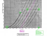
Although the pentode-mode specs allow 500V, I don't think this will translate into 500V for triode.
The WE data sheet gives maximum operating conditions as an envelope in the attached diagram, for class-A pentode.
See that the 60mA rating is already derated to 50mA at 300V.
For triode, the voltage can probably increase a bit, maybe 340-380V, but at 300B levels, I would expect real trouble.
Not only that, but the linearity will get much worse at high voltage. We need some real measured curves to see where the degradation sets in (this happens for almost any power tube, but the onset voltage varies a lot).
Personally, I would find some way of obtaining real measurements before spending money on transformers.
The fact that the data-sheet says explicitly that the class-A performance of the 307A was compromised in order to get good class-C operation is a warning. It gives us exactly zero confidence that the WE 307A can compete with the same company's 300B design, where class-A linearity was the actual design goal. But still, measured curves will answer this question, too.
Attachments
Linearity for driving the higher impedances seen with headphones is directly proportional to the B+ and Grid voltage operatig points (why the gm-70 model shows practically zero distortion driving any headphone.)
I still don't get this.
A 300B, for example, can produce 8W of power in a (reflected) load of 3k2. If the secondary of the OPT is designed for an output of 8R, the turn ratio is 20:1, and there will be 8V RMS at the secondary output. If the secondary is designed for 40R, the turn ratio will be about 9:1 and there will be 18V RMS on it. 18V RMS in 40R produces, of course, about 8W (18^2 / 40). So the 300B produces the required swing on the secondary to drive the HE6. If the headphones were 3k2 one could make a 'parafeed' arrangement, with a choke in the 300B place and couple to the headphone with a cap, and still have enough swing to pump the 8W into the headphones.
I am quite sure that indeed the GM70 can produce 6W with less distortion than a 300B does, and maybe that difference can be heard better on headphones and that is what you are after (lower distortion at 6W output). But it is not because a GM70 'matches' better with the headphone due to higher operating voltage, I think ?!
Can somebody explain what I am missing?
many thanks, Erik
Last edited:
The fact that the data-sheet says explicitly that the class-A performance of the 307A was compromised in order to get good class-C operation is a warning. It gives us exactly zero confidence that the WE 307A can compete with the same company's 300B design, where class-A linearity was the actual design goal. But still, measured curves will answer this question, too.
Yes and a WE engineer making a slight compromise in linearity in the 40's is better than anything we can expect with todays materials. Making god tools is largely materials engineering/science and they just don't make 'em like they used to ?
I still don't get this.
A 300B, for example, can produce 8W of power in a (reflected) load of 3k2. If the secondary of the OPT is designed for an output of 8R, the turn ratio is 20:1, and there will be 8V RMS at the secondary output. If the secondary is designed for 40R, the turn ratio will be about 9:1 and there will be 18V RMS on it. 18V RMS in 40R produces, of course, about 8W (18^2 / 40). So the 300B produces the required swing on the secondary to drive the HE6. If the headphones were 3k2 one could make a 'parafeed' arrangement, with a choke in the 300B place and couple to the headphone with a cap, and still have enough swing to pump the 8W into the headphones.
I am quite sure that indeed the GM70 can produce 6W with less distortion than a 300B does, and maybe that difference can be heard better on headphones and that is what you are after (lower distortion at 6W output). But it is not because a GM70 'matches' better with the headphone due to higher operating voltage, I think ?!
Can somebody explain what I am missing?
many thanks, Erik
Because there is no such thing as a 50 ohm FIVE Watt secondary, they only exist on web forums and possibly AudioNotes $2500 HE6 KIT.
Designing for 50 ohm phones that require 5 watts is the equivalent of asking for a 35 Watt SET into 8 ohms same requirements as far as primary voltage and trying to shave this down with a high DCR Secondary (lower ratio) does not work without going to extreme lengths such as double C-core amorphous whatever, stuff nobody can afford. Its easy to end up with a transformer thats about 60% efficient unless you have a deep wallet. Start looking at the 300B curves where 60% of the power is wasted. Only chance is A2 with 300B and under tubes.
Do you see why the GM70 and similar HV group of tubes is ideal for this task?
Hi Regal,
thanks for the explanation, so it is indeed mostly about DCR on secondary.
I agree that one needs a large double C core for 8W of Single Ended power when one wants wide response and low DCR. I had a pair of audionote OPTs that confirm that. IIRC Pieter (from tribute audio) spoke that his SE transformers for 300B have about 0,2R on the 8 ohm secondary. If that secondary is made of 4 0,8R windings in parallel, rearranging for series parallel would result in 0,8R DCR output on a 32 ohm tap. But indeed, those are expensive transformerts (even though a pair is still probably much cheaper than the HE-6).
But a 35W OPT for a GM70 will also be expensive. Maybe a 35W (SE) EI GOSS core costs less than a smaller (8W SE) double C-core, but it will be a monster, and those dimensions will make that each secondary winding will be long and therefore contribute to high DCR as well, I think (sorry, can't do the transformer math).
And a high voltage amp brings all other sort of costs - and risks - with it.
Now this all sounds very rational (and maybe it is just wrong), and at least in the audio hobby I am not rational myself (just trying to not kill myself and others with high voltages, but for the rest all sort of extravagancies are allowed), therefore I repeat that I only asked because I didn't understand.
many thanks! Erik
Yes and a WE engineer making a slight compromise in linearity in the 40's is better than anything we can expect with todays materials. Making god tools is largely materials engineering/science and they just don't make 'em like they used to ?
It's possible, but this could go either way!
My point was that we need some kind of reliable characterisation of the 307A - in triode mode - before dropping cash on the iron. Nothing about the data sheet suggests more than middling performance, and 50-70 years lying around soaking up gas does not improve anything - gassy grid current is noisy, for starters.
(I speak for myself, but) I don't see the worth in designing with an unknown quantity. Real curve tracing, like the Audiomatica samples linked earlier, will allow:
- meaningful (rather than anecdotal) comparison with 300B;
- checking grid current in ancient samples;
- checking the operating point (especially voltage) that gives reasonable linearity - before the high-voltage degradation sets in.
OTOH, the latest 300B EH Gold is very well made (a major improvement on previous issues), despite moderate cost, and sounds excellent, provided only that the B+ and Filament supplies are worthy of it.
And this 300B is a 40W anode, rather than 15W+ some fraction of 6W for G2. If we are looking for headroom in our head-fi, the 300B gives much more.
I suppose one could build with a 360V B+ and a 5000-ohm OT, and try them both.
But relying on a driver circuit that can only support 307A and not reach the extra for a 300B, seems like asking for trouble, IMV.
- Home
- Amplifiers
- Tubes / Valves
- The all DHT SET Headphone Amp