I have one channel up and running but its definately not enough heatsink with the standard bias scheme. The odd thing is that I get .323 volts across the source resistors instead of the normal .25 volts. While this extra bias surely translates into better sound any idea whats up here and why its so much higher? I am using IRFP240's and everyting else is as on the Aleph 30 schematic.
Mark
Mark
Mark A. Gulbrandsen said:I have one channel up and running but its definately not enough heatsink with the standard bias scheme. The odd thing is that I get .323 volts across the source resistors instead of the normal .25 volts. While this extra bias surely translates into better sound any idea whats up here and why its so much higher? I am using IRFP240's and everyting else is as on the Aleph 30 schematic.
Mark
something definitely isn't as on A30 schematic;
current through first mosfet in LTP (voltage across 390E resistor) ?
you certainly missed some resistor value
Banned
Joined 2002
Mark A. Gulbrandsen said:I have one channel up and running but its definately not enough heatsink with the standard bias scheme. The odd thing is that I get .323 volts across the source resistors instead of the normal .25 volts. While this extra bias surely translates into better sound any idea whats up here and why its so much higher? I am using IRFP240's and everyting else is as on the Aleph 30 schematic.
Mark
I think it is the design. First off the board is way to small to accommodate 6 fets. It is to cramped up to dissipate all that heat in such a small area. My Mini A's produce a fair amount of heat and that is only 2 fet's. I'd hate to see what 6 fets would do with a higher bias and more rail voltage.
The reason most aleph boards that are sold on here with external output device boards is because of this exact reason, Aleph's get hot.
I attached a picture of Brian's new aleph mini's that i built for him while i stayed there.
After 24 hours of break in and warm up, these things were up to a pretty good temp. I'll ask Brian to plug them in and check them with his thermal meter.
My point here is that peter has a good design but the flaw is that the boards a little to small and the A30's get hot. I bet it sounds good.
Attachments
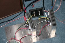
Mark A. Gulbrandsen said:I have one channel up and running but its definately not enough heatsink with the standard bias scheme.
Mark,
those are high efficiency heatsinks, they only work well with fans.
With a fan mounted on them you'll be amazed.
jleaman said:I think it is the design. First off the board is way to small to accommodate 6 fets. It is to cramped up to dissipate all that heat in such a small area.
My point here is that peter has a good design but the flaw is that the boards a little to small and the A30's get hot. I bet it sounds good.
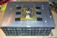
Your point is wrong. It's not the board that dissipates heat but the heatsinks.
Looking at the pic below I couldn't see a better way to arrange the mosfetsd on that heatsinks.
If bigger heatsink is required, I don't see a reason why not extend mosfet connection to the board with wires (that's how Aleph 0 was done).
It is also much better to run 3 x 3 wires (to each mosfet separately from small front end board) than 3 wires to 3 mosfets on additional output board (per side).
Besides, one should build the amps before commenting on the design.
Attachments
Banned
Joined 2002
Peter Daniel said:
Your point is wrong. It's not the board that dissipates heat but the heatsinks.
Looking at the pic below I couldn't see a better way to arrange the mosfetsd on that heatsinks.
If bigger heatsink is required, I don't see a reason why not extend mosfet connection to the board with wires (that's how Aleph 0 was done).
It is also much better to run 3 x 3 wires (to each mosfet separately from small front end board) than 3 wires to 3 mosfets on additional output board (per side).
Besides, one should build the amps before commenting on the design.
Ok, I'll just say this.
Mark your heat sink is way to small to work with this board. I think the only way this is going to work is if you used forced air into that heat sink.
There is absolutely NOTHING wrong with peters design! In fact his device spacking is farther apart than the O.P. device spacing on Jan's original KSA-50 board.. and that amp dissipates at least twisce the heat . Peter's board is not only an excellent design but also very ingenious. There is no disputing that fact!
Jacco is correct on this one. These sinks are amazingly efficient if one places a fan that blows up through it. I now have a small 2" computer fan running at half voltage and the whole thing is just luke warm! This sink was from a huge pulse width motor speed controller and it WAS fan cooled for that use.
As for a resistor in the wrong place... definately not as I measure each resistor before it gets soldered in place. My eyes are too bad off to see those tiny color bands . The fact that is all 6 mosfets have .320 give or take .07 volts on them.... I matched them very closely. My operational DC offset untrimmed was just under 5 mv, again due to use of my old but trusty gigantic 5-1/2 digit precision Racal DVM.
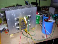
I will just leave the bias as-is for now. No need to lower it as long as I have the fan going. I am tempted to build a chassis that uses the fan to pressurize the whole chassis and allows the air to flow through the sinks and out of the case.... somewhat like a BGW 750 power amp... that always worked really well.
Mark
. Peter's board is not only an excellent design but also very ingenious. There is no disputing that fact!Jacco is correct on this one. These sinks are amazingly efficient if one places a fan that blows up through it. I now have a small 2" computer fan running at half voltage and the whole thing is just luke warm! This sink was from a huge pulse width motor speed controller and it WAS fan cooled for that use.
As for a resistor in the wrong place... definately not as I measure each resistor before it gets soldered in place. My eyes are too bad off to see those tiny color bands
. The fact that is all 6 mosfets have .320 give or take .07 volts on them.... I matched them very closely. My operational DC offset untrimmed was just under 5 mv, again due to use of my old but trusty gigantic 5-1/2 digit precision Racal DVM.I will just leave the bias as-is for now. No need to lower it as long as I have the fan going. I am tempted to build a chassis that uses the fan to pressurize the whole chassis and allows the air to flow through the sinks and out of the case.... somewhat like a BGW 750 power amp... that always worked really well.
Mark
Attachments
Banned
Joined 2002
Mark A. Gulbrandsen said:Jacco is correct on this one. These sinks are amazingly efficient if one places a fan that blows up through it. I now have a small 2" computer fan running at half voltage and the whole thing is just luke warm! This sink was from a huge pulse width motor speed controller and it WAS fan cooled for that use.
As for a resistor in the wrong place... definately not as I measure each resistor before it gets soldered in place. My eyes are too bad off to see those tiny color bands
I will just leave the bias as-is for now. No need to lower it as long as I have the fan going. I am tempted to build a chassis that uses the fan to pressurize the whole chassis and allows the air to flow through the sinks and out of the case.... somewhat like a BGW 750 power amp... that always worked really well.
Mark
maybe you can make your chassis so your air flows up words with a 5" fan i the middle running at 4V. 4v will me quiet but also move air to keep them cooler.
Have the chassis hold the heat sinks fin's to fins. Like peters tower he created with the A30's using this same board. he strapped them together and put a fan in it. Make your chassis flat and have a metal grate over top to allow cold air in bottom and hot air out the top.
Peter's board looks really nice mounted like you have it. Good job on the board peter.
The BGW 750 had just a four sided steel chassis. The power supply and protection circuit is in the bottom and each channel's heat sink bolted on top... there was a 1" gap between both of them in the center. Then a top copver was placed over the sinks sealing them in with only the air inlet between them. The rear mounted fan on the back of the chassis blew into the chasiss through the sinks and out the perforated top sides. Very simple and effective.
Mark
Mark
Mad_K said:
add some extra gate resistors
I fully support. I made my F1 with paralled mosfets, but missed the gate resistors. Oh my . . . the paralled mosfets were facing directly gate-to-gate. Sht! I got nice parasitic oscillation (when large signal was given). Later, I fixed the gate resistors for all mosfets . . . and the sht cleaned up . . .
")
Still cross-country snow there . . . ?
jh6you said:I would go with the better thermal effect, instead of the better cosmetic.
Cosmetics is not an issue...but electrical versus thermal stability

I think that your wires will not run out of the box.
You will intentionally have the wire length short inside.
You will solder the gate resistor directly to each gate.
If so, you could manage a better thermal distribution at
not any cost of electrical stability . . . just my small opinion . . .

You will intentionally have the wire length short inside.
You will solder the gate resistor directly to each gate.
If so, you could manage a better thermal distribution at
not any cost of electrical stability . . . just my small opinion . . .
- Status
- This old topic is closed. If you want to reopen this topic, contact a moderator using the "Report Post" button.
- Home
- Amplifiers
- Pass Labs
- The Aleph30 PCB layout