Grey,
Can I ask a dumb dumb Question,
All these post have go me confused. it must be the negative gravity problem we have down under here mate or the vapours from my moonshine in the bathroom, by God its a good drop. I must mail some to Neslon for evaluation!
Can I assume each fet for the front end is biased for 10 ma each so they are sharing 20ma from the CCS? Or are we talkin 20ma per fet, I mean Hello?
ie I have never meaured the ccs value in situ
Ian
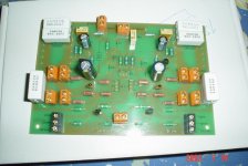
PS A peck at first board off the macka Line, by the way all the credit goes to John Inlow,
Three Cheers for John Guys.
Can I ask a dumb dumb Question,
All these post have go me confused. it must be the negative gravity problem we have down under here mate or the vapours from my moonshine in the bathroom, by God its a good drop. I must mail some to Neslon for evaluation!
Can I assume each fet for the front end is biased for 10 ma each so they are sharing 20ma from the CCS? Or are we talkin 20ma per fet, I mean Hello?
ie I have never meaured the ccs value in situ
Ian
PS A peck at first board off the macka Line, by the way all the credit goes to John Inlow,
Three Cheers for John Guys.
Attachments
hmmm, without seeing a schematic, I'm going to guess that
It's that a pretty bad idea to guess what someone is asking before attempting to answer him?
"Resistor underneath"
What...... are you talking about a resistor connected to the drain or the source of the Jfet.
"FETs are delicate, feminine things that swoon if you point more than 5 or 10mA at them." Jfets are available with Ids (saturated drain current) values up to
When talking in the same post about Jfets and mosfets please don't use the term FET since it is unclear which device type you are refering to. Jfets are available with Ids values of up to 60mA (for the U310) and the jfet will operate with a drain current less than its Ids quite well within resonable power dissapation. The popular 2SK170 V has an Ids from 10mA to 20mA and would not "swoon" in the above situation. I heard Jfets are quite popular for audio small signal applications like amplifier front ends and current sources for example.
Max
JH,
A valid strategy. If you use two current sources, you will gain a little more control over the two sides of the differential, but at the expense of having to use balanced inputs, since the two sides of the differential won't communicate as freely with the resistor in place.
If you've got a balanced source, go for it.
Ian,
You want confusion? Try listening to a tube guy and a solid state guy talk about bias. The tube fellow will speak in terms of volts at the grid, whereas the solid state critter will talk about current through the device. They're both right, but the cultural differences do tend to require translation sometimes. You'll probably catch me doing both from time to time (perhaps even in the same post), since I tend to think tubes, then translate to solid state. Hopefully, people can make allowances.
At any rate, the current source supplies 20mA total. Half of that goes through each side of the differential, i.e. 10mA for each IRF9610.
The price for this valuable information is a quart of 'shine.
The morning sun slanted across the desert faster than a jack rabbit, illuminating each sagebrush as though it was the most important weed in the Territory. The stranger slung his saddle bags over Aleph's back and prepared to mount, but paused, hearing two voices behind him, arguing about how many ounces of sugar were in a pound.
He shook his head, pitying the shopkeeper who had to face such a tirade so early in the morning.
Minutes later he was riding out of town, headed for the Molding Hills, still chuckling to himself.
Grey
P.S.: For those who might have been confused, I was thinking in terms of an N JFET since most, if not all, examples in books show Ns, and John specified that he was looking in a book. For that matter, most JFETs are Ns even out here in the real world.
Under, in the case of an N JFET, will generally be seen as the Source. Unless you're in Australia. Never been there. They might draw them pointed the other way for all I know, just to assert their individuality and independence. You never know about those Aussies.
Lack of a J doesn't keep a JFET from being a JFET, although pendants might see it otherwise. I used FET because John used FET. I trust that my use of the term MOSFET in the same post allowed most folks to keep one distinct from the other.
I've had a batch of power JFETs on order for years. They keep pushing the delivery date back. Current estimate is that I'll receive them around the year 2019...maybe.
Somebody dropped me a note asking for a clarification of
"differential DC" and "absolute DC" at the outputs of an
X type circuit:
Differential DC offset is the quiescent DC value between the
two balanced outputs. This is what the speaker sees. If
both outputs are at +1.00 volts DC, their differential DC
offset is at 0.00 V.
Absolute DC offset in the above example is +1.00 volts.
Differential values are ideally 0, but practically speaking, less
than 100 mV is a pretty acceptable number most of the time.
Absolute DC is also desired to be at 0, but practically speaking
it can wander around a wide range without significantly
affecting performance. As this gets large, it starts cutting into
the maximum voltage swing of the amp.
Re: Grey, please explain your offset circuit.
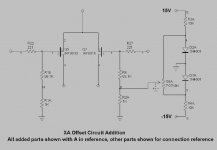
By Vv2 I suppose you the pot that adjust the current source for the front end. That pot adjust the absolute DC offset. the circuit shown adjust the differential or relative offset across the speaker. It is only necessary to have the circuit on one side of the diff pair and it can compensate for a positive or negative offset voltage. I think the inputs to the 10K resitors or the actual input signal for the amp should be Ac coupled for this to work best. Looks like a good way to trim the relative offset without changing other parameters in the amp. Kudos Mr. Rollins.
Max
carpenter said:It's a lovely drawing, but I'm unable to fully grasp what you're offering to the group. Also, is this circuit located only on one side of the diff. pair? Does it work in concert with V2?
Thanks a bunch,
John
By Vv2 I suppose you the pot that adjust the current source for the front end. That pot adjust the absolute DC offset. the circuit shown adjust the differential or relative offset across the speaker. It is only necessary to have the circuit on one side of the diff pair and it can compensate for a positive or negative offset voltage. I think the inputs to the 10K resitors or the actual input signal for the amp should be Ac coupled for this to work best. Looks like a good way to trim the relative offset without changing other parameters in the amp. Kudos Mr. Rollins.
Max
I'd like to ask this question one more time...
On the inductor that I posted info about on pages 118 and 119, would it be possible to parallel the windings to increase the load carrying capacity?
Does this reduce the mH value by half? Would it still be good enough for our purposes?
Would this be an acceptable way to use this choke or should I simply shop for larger ones?
What is your recommendation????
Still learning at this end...
Thanks very much for the help?
Offset Circuit
Yes
Yes but let me know how long it takes to get a pair within even 10mV match.
Hey I just noticed something..... who the heck is "G Rolins"? That's not Grey and it is not funny! What gives?
Max
carpenter said:Does this circuit correct imperfections in the FET (9610) match? If the 9610s were matched perfectly, wouldn't they have 0 volts offset in their combined properties?
John
Yes
Yes but let me know how long it takes to get a pair within even 10mV match.
Hey I just noticed something..... who the heck is "G Rolins"? That's not Grey and it is not funny! What gives?
Max
Apogee said:Peter,
Look at the Aleph X offset schematic that was posted....
Post # 1785...
He tricked me here.
") I was looking at it and was sure it was Grey. The only thing that didn't match was the way the schematic was drawn, it reminds very much everything that HH was posting. I'll send the post to purgatory and post the schematic again.
I was looking at it and was sure it was Grey. The only thing that didn't match was the way the schematic was drawn, it reminds very much everything that HH was posting. I'll send the post to purgatory and post the schematic again.Here it is. Nothing better than a man himself describing the circuit:
"By Vv2 I suppose you the pot that adjust the current source for the front end. That pot adjust the absolute DC offset. the circuit shown adjust the differential or relative offset across the speaker. It is only necessary to have the circuit on one side of the diff pair and it can compensate for a positive or negative offset voltage. I think the inputs to the 10K resitors or the actual input signal for the amp should be Ac coupled for this to work best. Looks like a good way to trim the relative offset without changing other parameters in the amp. Kudos Mr. Rollins."
"By Vv2 I suppose you the pot that adjust the current source for the front end. That pot adjust the absolute DC offset. the circuit shown adjust the differential or relative offset across the speaker. It is only necessary to have the circuit on one side of the diff pair and it can compensate for a positive or negative offset voltage. I think the inputs to the 10K resitors or the actual input signal for the amp should be Ac coupled for this to work best. Looks like a good way to trim the relative offset without changing other parameters in the amp. Kudos Mr. Rollins."
Attachments
Thanks for your kind response.GRollins said:JH,
A valid strategy. If you use two current sources, you will gain a little more control over the two sides of the differential, but at the expense of having to use balanced inputs, since the two sides of the differential won't communicate as freely with the resistor in place.
If you've got a balanced source, go for it.
By the way, the two CCS's will form almost infinite impedance. Therefore, the R to be introduced between the sources will not interrupt the communication between the two MOSFETs. So, the unbalanced signal source will be also accepted without any special problem. What is your opinion to this comment? Thanks again.
JH
DISCLAIMER:
I dropped by the Pass Labs web site to read the product literature for the new Rushmore speaker. It says that the amplifier driving the 15" cone is an "Aleph X" circuit.
I would like to take this opportunity to remind people that the circuit that I posted at the beginning of this thread is in no way to be considered an official Pass Labs product. I have not seen a schematic for any of the XA series amplifiers. Nelson gave me a hint (thanks, Nelson) about the resistors at the outputs. I had tried it with 1k resistors and given up, going on to other strategies. Nelson suggested 30 ohms so I revisited the idea and it came together. That is, to my recollection, the only hint I received about getting the DC offset problem under control, and he certainly never sent me even part of a schematic. The circuit is just something I made up on my own, staying up late at night puttering around with a bunch of parts.
To put it more plainly, this amplifier is not to be construed as being the amplifier in the Rushmore speaker. (For that matter, the Mini-A is not to be regarded as being related to the smaller amps for the other drivers.)
When I was casting about for a name to call this thing, I wanted to make its heritage obvious. The XA200 had been announced, but was not yet shipping, and all I knew at the time was the name. My thinking was that if Nelson was going to call the real thing the XA, then I wanted to call this circuit something different. Between needing to get in 'Aleph' and 'X,' and yet stay away from the moniker XA, I decided simply to call it the Aleph X. I chose that order because it was both alphabetic (A before X) and chronologic (the Alephs hit the market before the X products came out). It may not make a good movie poster, but it seemed a servicable name to me at the time.
Besides, I'm sure Nelson has conjured up another trick or three to advance that circuit beyond anything I managed to do here in the hinterlands.
All right, lemme see where I was earlier...
JH,
It's not the impedance of the two current sources--that's fine. I think you'll find that the resistor between the two Sources, unless it's really small (in which case it doesn't really separate the two halves of the differential), will interfere with the signal crossing from the Source of the driven side to the Source of the undriven side. As a result, the front end won't function very well as a phase splitter.
The feedback will correct this to some degree, but I wouldn't want to bet the farm on getting a good, balanced drive to the two halves of the amplifier.
By all means, give it a shot if you've got time and parts. You don't have to build the whole amp--just throw together the front end and measure the output from the two sides.
John,
Testing the parts <i>in situ</i> means actually putting them in the circuit and seeing how well they perform. It's a pain in the neck, but it will guarantee that things work well together.
Grey
Hi Grey,
How does one test the 9610s in situation?
Fred posted an idea a few pages back that allows adjustment to the two MOSFETs in the differential pair up front. Assuming one were to implement this circuit, or simply measure and change out MOSFETs for that matter, how would the measurements take place?
Many thanks as always,
John
- Home
- Amplifiers
- Pass Labs
- The Aleph-X