If you have 5V your gain transistors will conduct more than current source transistors and on outputs you will have negative voltage compared to ground beacuse bias current will produce less voltage drop on gain devices than current sources.
If you have to keep output voltage close to 0V compared to ground you must keep both CS and gain transistors in almost same conducting condition.
If you have to keep output voltage close to 0V compared to ground you must keep both CS and gain transistors in almost same conducting condition.
Stefan,
I don't think is that simple. I haven't really been able to overbias the gain mosfet, there seems to be "something" holding them back. I found the opposite far more prone to happening I think that is likely due to the interaction with the differential and the fact that the two sides are tied in together.
One thing is for sure a two gain stages design can be plenty complicated!")
I don't think is that simple. I haven't really been able to overbias the gain mosfet, there seems to be "something" holding them back. I found the opposite far more prone to happening I think that is likely due to the interaction with the differential and the fact that the two sides are tied in together.
One thing is for sure a two gain stages design can be plenty complicated!
stefan said:If you have 5V your gain transistors will conduct more than current source transistors and on outputs you will have negative voltage compared to ground beacuse bias current will produce less voltage drop on gain devices than current sources.
If you have to keep output voltage close to 0V compared to ground you must keep both CS and gain transistors in almost same conducting condition.
That's why you adjust the absolute offset by changing current to differential pair. It can be done very easily.
forgive me if I have misread something, but what the heck are you guys talking about?!
If you run more current through the front end, you still have to adjust the load resistors in the front end to get the voltage to be at zero at the speaker terminals (referenced to ground). If you change the resistors that go from the sources of the front end gain transistors to the outputs, it will vary the amount of current you have to put through the front end to get to that 0v on the output, but the gate- source voltage on the output gain mosfets still is at exactly the same voltage... or at least that's what I have found. So, what am I missing here? Is there another variable in the circuit that adjusts that voltage without screwing up the balance point on the output? Isn't it completely dependant on the output mosfet's turn-on characteristic?
If you run more current through the front end, you still have to adjust the load resistors in the front end to get the voltage to be at zero at the speaker terminals (referenced to ground). If you change the resistors that go from the sources of the front end gain transistors to the outputs, it will vary the amount of current you have to put through the front end to get to that 0v on the output, but the gate- source voltage on the output gain mosfets still is at exactly the same voltage... or at least that's what I have found. So, what am I missing here? Is there another variable in the circuit that adjusts that voltage without screwing up the balance point on the output? Isn't it completely dependant on the output mosfet's turn-on characteristic?
They're playing with various "what-if" scenarios. Nothing to worry about.
Peter, as I recall, ran up the current to his front end, but used lower value load resistors to compensate.
The amount of feedback (the 100k resistors grataku refers to) can be used change the gain of the amp or change the sound of the amp (it also gets into other things like damping factor). If you increase the value of R16 & R30 (the feedback resistors) while leaving all else the same, you end up decreasing the feedback and increasing the gain of the amp. Or <i>vice versa</i>.
The exact voltage you go for across the differential load resistors doesn't have to be 4.0V exactly. I was just using nice round numbers for the example.
Stephan's post about current sources being a reasonable approximation of an infinite resistor is quite correct. It's called active loading. Works well. However, there's a limit as to how many variations on a theme I can reasonably put in one post and not get so tangled in the permutations that the post is unreadable. It's bad enough, already.
If you get the balance between the output MOSFET and the current MOSFET too far out of whack, the output junction will start pulling or pushing a substantial amount of current through the grounding resistors at the outputs. It's a good idea to make these able to carry a fair amount of wattage before cooking. They can end up getting <i>very</i> hot if the amp is out of adjustment.
Grey
grataku,
Yes, you have negative feedback trying to keep output voltage and returning the circuit to stable condition.
But don't you think that the circuit will work better if it's well balanced even without using negative feedback?
In this case work of negative feedback to provide constant output voltage will be minimised.
John,
Your posts have slid off the bottom of the screen, but I'll try to answer what I can remember...
--There's no need to use a 2SJ109 for the current source. Current sources are independent entities--building blocks, if you will--and you're free to substitute any combination of parts that suits you. The existing IRF9610 will do a nice job of supplying current to any new differential that you're likely to want to try. All you need to do is adjust the value of the resistance under the Source (the three resistors taken as a whole) to set a new operating current.
--The voltage drop across the front end load resistors will not change because the circuit uses a current source and a current source will do everything in its power to keep the same amount of current flowing, no matter what the rail voltage does. If you substituted a resistor for the current source the current would change if you changed the rail voltage.
You can use a resistor if you want to, but you'll have to set the value according to whatever rail you intend to use. You'll also be pretty much forced into using a balanced signal to drive the amp, as the front end won't make a very good phase splitter with just a resistor to supply current.
As a more concrete example, if you stay with the original 15V rail, and subtract about 4V for the Vgs of the input MOSFETs, you'll end up with 11 volts. Then it's time to crank up Ohm's Law again: 11V/.02A= 550 ohms. Call it 560 ohms. (Don't forget that the current source is supplying current for both sides of the differential at 10mA each, so the total is 20mA.)
The differential will run quite nicely like this, but you'll find that a single-ended input doesn't drive both halves of the amp; only one half. The other side will receive a feeble signal and won't carry its part of the load. To get a differential to function as a phase splitter (any circuit that takes a single-ended signal and gives you two equal, out-of-phase outputs--there are numerous other phase splitter circuits), you need a pretty hefty amount of resistance under the tail. A few tens of thousands of ohms will get you started.
So, let's see...uh 47k under the tail...20mA...sure, no problem...all we need is a 950V rail!
Even speaking as a tube kinda guy, I find the prospect daunting.
It's easier to use a current source for this circuit. It gives you something approximating infinite resistance and better CMRR. The downside is that it's noiser than a resistor and has it's own little personality problems, like questions of compliance (over what range of voltages will this thing behave the way you want it to?), and a minor increase in complexity and cost over a single resistor.
Life's full of compromises. Choose the ones that come closest to your needs.
Grey
Power Supply Question????
I've located a few of these and am curious if they would be a good fit for the Aleph-X (and also original Aleph) power supplies...
Opinions???? I have requested the winding resistance but don't know it at this point in time...
The price is right!!!
Thanks...
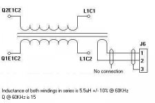
"2.6uH @ 60KHz, 10A continuous, 100A max peak. This inductor/choke is designed for high current applications (but can be used for low current as well). It is constructed of a toroidal ferrite core with 14 gage wire wrapped around the toroid donut."
I've located a few of these and am curious if they would be a good fit for the Aleph-X (and also original Aleph) power supplies...
Opinions???? I have requested the winding resistance but don't know it at this point in time...
The price is right!!!
Thanks...
"2.6uH @ 60KHz, 10A continuous, 100A max peak. This inductor/choke is designed for high current applications (but can be used for low current as well). It is constructed of a toroidal ferrite core with 14 gage wire wrapped around the toroid donut."
Attachments
 Very clean explanation. Thanks.
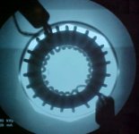
Thanks for the info, Grey.
I've been boning up on amplifier theory "Practical Solid State Circuit Design; Jerome E. Oleksy". It will be awhile before I have it down. At least I have a source to follow so that I can take measurements on your AX design and using Ohm's law, perhaps begin to understand how you made it all happen.
You could keep me interested for a long time by continually spelling out what does what and why it's necessary; from the top to bottom. I would love to see your notes as you created this jewel. I can fabricate amplifiers to my heart's desire, but truly understanding the beast would be even more rewarding.
John
A bit more info...
Am planning to build a couple of AX's the are pretty close to the XA-200... The plan is configure them so that they are very comfortable running a 4 ohm load...
Are these big enough? What about paralleling the windings? Would this work?
Thoughts?
Thanks,
Am planning to build a couple of AX's the are pretty close to the XA-200... The plan is configure them so that they are very comfortable running a 4 ohm load...
Are these big enough? What about paralleling the windings? Would this work?
Thoughts?
Thanks,
All right, I've got a spare moment, let's tilt at windmills and break this thing down into functional units. Hell, I should have done this eons ago.
Taking it from the front end:
Differential--Q5, Q7, R23, R25
Current source--D1, R17, R20, Q6, R24, R26, V2
Protection & anti-ground loop--D2-5, R21
Input network--R18, R19, R28, R29
Feedback--R16, C2, R30, C4
Current limiting/fault protection--R10, R13, Q4, Q9, R35, R39
Output--Q2, R6, R9, R38, R41, Q11
Aleph current source--R2, R3, Q1, R5, R7, R8, V1, R11, R12, C1, R14, R15, Q3, C3, C5, R31, R32, Q8, V3, R33, R34, C6, R36, R37, Q10, R40, R42, R43
Output grounding/DC offset control--R1, R4, R44, R45
I think that got everything. Yes, you can quibble a bit about some of the groupings, like whether R6 and R41 ought to be included in the limiting/protection unit for instance, but it'll do for a start. If you want to, circle each group on the schematic with a pencil.
Some units, like the Current source, are completely, absolutely up for grabs. Wanna put in a different current source? Knock yourself out. Pull out the parts I listed above and insert the current source of your choice. Your one and only concern is that your new current source deliver something on the order of 20mA and be a bit variable. Unless you want to start changing other things...
The Aleph current source is really the only unusual thing, and the patent is actually pretty readable. Get yourself a drink, the patent, and a schematic of any of the Alephs and sit down for a bit. Take a load off your feet and let your mind do the work. Just stare at it for a while until it comes to you. If that doesn't work, post and I'll give it a try.
While you're at it, raise your glass in the general direction of California and thank Nelson for letting us play with this stuff.
I was in a hotel room in Asheville, NC reading the Aleph patent late one night after everybody else had conked out. It was the first peace and quiet I'd had in days, and once I got through the patent it took all the willpower I could muster not to shake 'em all by the shoulder and yell "Eureka" in their ears.
They'll never know how close they came...
The X part is nothing more than the way I ran the feedback across from one side to the other. (What do you mean you can't see it...see the little x in the middle? Ha! Proof! It must be X, 'cause it's an X!) That patent is a little more obscure to read. It's because the concept is simpler, you see. They've got to go to extra trouble to make it unreadable so that the terrorists don't get hold of the concept. Don't let that stop you. You're not a terrorist, are you?
Don't bother looking for the magic resistor that the patent says stops the 'hall of mirrors' effect. It ain't there. Don't need it this time around.
The Outputs are nothing special. That's a normal way to hook up a gain device--grounded Source. Wanna put in bipolars? Okay. Tubes? Okay. Just be sure that you make some adjustments so that they bias up properly and you'll be fine.
Having a differential is pretty much necessary, it's inherent in the X scheme. Besides, it's a nice, elegant way to do the feedback, the phase splitting (if needed), and get some gain going, all in one compact package.
The Current limiting/fault protection unit can be removed entirely if you want. The Protection and anti-ground loop stuff, too. Just be careful with static at the front end if you take it out.
Incidentally, you can do voltage feedback to the Aleph current source instead of current feedback and it'll still be Aleph. But that's another story.
Grey
the stuff of dreams......
Grey!
This is what I'm talking about! Thank-you-very-much!
John
In the book I'm studying, the author uses much, much higher resistor values to bias up the front end. I think he's trying to stress the point that FETs are voltage controlled devices and don't require much in the way of current. Yet, the AX seems to use considerably more current to bias and control the circuit. Would you mind sharing your thoughts on the matter?
Higher resistor values to bias...hmmm, without seeing a schematic, I'm going to guess that you're talking about a simple grounded Source FET with a comparatively large (I dunno, what, 2.2-10k?) resistor underneath, depending on the rail.
Okay, look at it like this. To a first approximation, consider the voltage from the negative rail (I'm assuming a bipolar power supply) to ground as a voltage that needs to be traversed by a resistor in order to set the bias. Let's say that's 15V.
Suppose you want 4mA of current through your FET.
15V/.004A=3750 ohms
To fine tune it, you can start adding in Vgs, etc., not to mention having to work with real resistor values, but for the moment we'll just say that you'll want a 3750 ohm resistor for 4mA.
Okay, now take a MOSFET. Something like the IRF9610 in the Aleph-X differential can take entire amps before it comes apart. FETs are delicate, feminine things that swoon if you point more than 5 or 10mA at them. The 9610 is a big, hairy weight lifter by comparison.
You could, in principle, bias the MOSFET front end to a couple hundred mA (watch the heat!) without batting an eye.
It's not so much a question of voltage as current.
Grey
- Home
- Amplifiers
- Pass Labs
- The Aleph-X