Hi ojg,
just about to finishing my first 2 preamps! Thanks for that great project, I am really enjoying it so far!
I do have one question though (sorry if this was posted already): I really like working with the interactive BOM but I think the mouser codes aren't correct anymore with the rack version (especially the gain resistors!). I got a bit confused first but after double checking with the schematic I assume that the values are correct and the mouser codes wrong? Maybe it would be nice to go through the BOM again, also bc some of the parts are end-of-life ones.
Thank you!
Matthias
You are absolutely right! Thank you for checking.
The values match the gains suitable for THAT1512, while the Mfr Part Nr matches the gain values for THAT1510 which was used in the desktop version.
When in doubt, trust the values!
It would be great if you could help out and update the Mfr Part Nr with the correct parts that matches the value, it is an open source project after all!
If you are not used to dealing with Github and pull requests, you could post the corrections here and I could do the upload.
Here is my take on 2 of the preamps. The only thing I added is a little lens for the phantom-led to have the front more "closed". The knobs are a bit to long but I loved the colorscheme so I kept them.
Thanks for the cool project, loved working on it!
As for the mouser-codes, I am willing to help but it's true that I am not (yet) very much used to work with github. So I will have to post the codes here.
Best,
Matthias

Thanks for the cool project, loved working on it!
As for the mouser-codes, I am willing to help but it's true that I am not (yet) very much used to work with github. So I will have to post the codes here.
Best,
Matthias

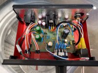
I made a slightly modified version of this mic preamp. I added a boost converter (LT8362) to generate 48V from lower input voltage. According to simulations (and datasheet) 8V seemed to be the lowest possible for 48V output. So to be able to use power banks I also added a USB PD sink controller (STUSB4500) so that USB PD power banks with >9V output could work as well. I had done similar stuff in my silentswitchers so I could more or less copy those designs.
When I started testing with USB PD power bank I noticed that the current draw at 12V input is so small that the power bank will switch off after few seconds. But to my amazement it works also with 5V input. So regular 5V power banks or even USB port can be used for power.
Here is a picture of the board.

Boost converter and USB PD controller are at top left corner. Power connector is USB-C. Apart from elkos and THAT1512 I've used SMD components. Resistors are MELF and capacitors C0G.
Performance seems to be very similar to the original. Here is THD vs Frequency at 40dB (input -40dBFS).

When I started testing with USB PD power bank I noticed that the current draw at 12V input is so small that the power bank will switch off after few seconds. But to my amazement it works also with 5V input. So regular 5V power banks or even USB port can be used for power.
Here is a picture of the board.
Boost converter and USB PD controller are at top left corner. Power connector is USB-C. Apart from elkos and THAT1512 I've used SMD components. Resistors are MELF and capacitors C0G.
Performance seems to be very similar to the original. Here is THD vs Frequency at 40dB (input -40dBFS).
Nice one, bohrok2610!
Nice to see some derivative work. I have also pondered about different USB-C to 48V solutions. The 5V, 3A you get from USB-C without a PD controller is sufficient. I tested the LT8302, which is an isolated flyback converter, and that worked, but I think it is too expensive for a solution that I want to publish.
I wonder though if it could be retrofitted as a plugin-board to my existing design. And there would be the option of having it externally for those worried about switching noise inside their preamp.
I hope you plan to honor the CC-BY-SA license, and publish your design files as well, bohrok2610. Either here or on Github. Looking forward to seeing them.
No worries, I went ahead and updated the BOM files on Github with the right parts for the 1512 version.As for the mouser-codes, I am willing to help but it's true that I am not (yet) very much used to work with github. So I will have to post the codes here.
No problem. I use DesignSpark so no KiCad files.I hope you plan to honor the CC-BY-SA license, and publish your design files as well, bohrok2610. Either here or on Github. Looking forward to seeing them.
Attachments
@ojg amazing project! Maybe it's time to start offering built kits? I would love to buy one.
I have given this some thought, and here is what I have figured out.
1. I am not going to do kitting of parts and selling those. I do not have experience with kitting, but I foresee that it is quite time consuming. I wouldn't be able to charge enough for it to be worth my time. Companies like Mouser and Digikey are very good at kitting, that is their whole business, so it's just better to buy from them.
2. My goal with this design was to use common, basic parts as much as possible. That way I thought most builders would have at least some of the parts in their parts drawer already. That way they would not need to order an entire kit, only the missing parts. And that is best done through Mouser/Digikey.
3. I do see the point of supplying bare PCBs though. Becasue if you just want one or two units it's a bit wasteful to have to order a minimum of five PCBs from a PCB factory. I could order a large batch of PCBs and sell those one by one. It could be mailed in a regular envelope so shipping is affordable. I'll look into doing this if there is interest.
OJG
The boost regulator on my board could quite easily be made into a plugin-board. SilentSwitcher boards have very similar DC converter operating at same switching frequency (2MHz) so I would not expect any switching noise even when placed inside the chassis. USB PD controller can be left unpopulated if not needed. Besides it needs to be preprogrammed through I2C so not very easy for diy.I wonder though if it could be retrofitted as a plugin-board to my existing design. And there would be the option of having it externally for those worried about switching noise inside their preamp.
Nice project ! What do you guys think about putting a 1k logarithmic potentiometer at the output of the THAT, the latter always amplifying at 60dB? That would permit to not be limited by the reverse log taper availability. How bad would this be? I can't see why would we loose performance on noise.. Okay maybe a bit loose of SNR but not that much.
By always amplifying with 60dB you run the risk of clipping the signal in the THAT preamp. Choosing the gain in the mic preamp is always a tradeoff between SNR and headroom, and by having a fixed gain and then attenuation that tradeoff can't be adjusted.
The ThatMicPre design with its switched gain avoids the need for a reverse log taper potentiometer.
The ThatMicPre design with its switched gain avoids the need for a reverse log taper potentiometer.
Of course there's always this tradeoff, but typical output voltage swing of 1510 is said to be +/-13.3V, so I think we still may have plenty of headroom to go with that (at least 10dB). Further than that, we would keep best noise performances everytime as we are at 60dB. I'm not trying to debunk the switched gain solution, just to know if there's another interesting one for this chip.Choosing the gain in the mic preamp is always a tradeoff between SNR and headroom, and by having a fixed gain and then attenuation that tradeoff can't be adjusted.
Hey everyone, I tried to build this as a first diy project. Everything seemed to be going good so far, but after a first test, I must've done something wrong. There is no output at first. When i turn phantom on (led green), the preamp makes a loud squeak. When I turn phantom off, I get an output for 5 seconds, before the audio gets distorted an progressively dies.
Would anyone have a clue of sections/components to check first?
Thanks so much!

Would anyone have a clue of sections/components to check first?
Thanks so much!
huangok2023 and hanyang, thank you for sharing your builds!
antoine_glis: That's unfortunate. Let's try to figure it out together. I can't see anything immediately wrong from your picture. Do you have a multimeter? Can you measure the DC voltage at the nodes where it says V48P and V35P?
antoine_glis: That's unfortunate. Let's try to figure it out together. I can't see anything immediately wrong from your picture. Do you have a multimeter? Can you measure the DC voltage at the nodes where it says V48P and V35P?
- Home
- Design & Build
- Equipment & Tools
- ThatMicPre - an open-source mic preamp