Hmm, I just went through some of the design notes. The compressor one (dn115) does sound pretty interesting - of course I don't have the slightest idea how to translate those schematics to a PCB. However, it seems to me like a compressor (maybe even stereo..) could be equally popular as the preamp.
As for the 48V PSU, I ordered a fairly inexpensive one that does a pretty good job so far - I don't know if the benefits of building one outweigh the time and effort.. Then again, my view on things is a rather naive one considering my day job as theater composer/pianist.
As for the 48V PSU, I ordered a fairly inexpensive one that does a pretty good job so far - I don't know if the benefits of building one outweigh the time and effort.. Then again, my view on things is a rather naive one considering my day job as theater composer/pianist.
There is some very interesting projects on Group DIY (Green mic preamp, SSL 9k and way more)but as they are old ones a lot of the links are dead and the projects are not always well documented. The Gyraf G9 is also an interesting option, it's a DIY tube mic preamp.
Indeed a compressor/limiter would be interesting. It has already been made in other projects like the Pico Compressor or one following the DN115(http://diy-tubes.com/index.php?route=product/product&path=59&product_id=683). I don't how much of an upgrade it would be from a plug-in.
In my opinion it would be very interesting to try some kind of a state of the art preamp based on, for example, the Graeme Cohen topology (look for Samuel Groner's work). I'm sure it could be possible to come up close to the very expensive ones.
I really appreciate the direct +48V approach, it simplifies everything.
Hi Azrod23,
Internally the THAT1510/12 preamps use the same topology as the Graeme Cohen design for it's first stage, see fig 2 in the datasheet. A discrete design using transistors and opamps could make it possible to eke out 1 or 2dB less noise. It's an interesting engineering challenge for sure, but I'm not sure if that's what most DIY builders need or want?
Another variant of a microphone preamp would be to make a fully featured one with stuff like as switchable highpass filter, input pad, instrument input, VU/peak meter etc. The cost and size and complexity would increase, but it might still be interesting to some?
The benefit of an analog compressor/limiter over a plugin, is that it's between the preamp and the computer soundcards ADC. So you can turn the gain up on the preamp without risking clipping the ADC. The difficulty with analog compressors though is that you can't really objectively measure if it's any good, it's all subjective.
I found this thread thanks to @mahtew . Based on the specification posted in the top post by @ojg , ThatMicPre exhibits EIN=-128.3 dbU @ 60 dB of gain.
Are there any open source efforts to match the state-of-the-art preamps of interfaces like MixPre 3/6/10 II, capable of -128 dbU EIN @ 76 db of gain [1]?
Appreciate any feedback.
[1] https://www.sounddevices.com/mixpre-3-ii-specifications/
Are there any open source efforts to match the state-of-the-art preamps of interfaces like MixPre 3/6/10 II, capable of -128 dbU EIN @ 76 db of gain [1]?
Appreciate any feedback.
[1] https://www.sounddevices.com/mixpre-3-ii-specifications/
Even though it is counter intuitive, higher gain does not negatively impact the EIN. Indeed, the EIN is worse at lower gain (here 98,5 at 0db of gain for THAT 1510). So -128 dBU at 76dB of gain is not better than ThatMicPre's -128,3dbU.
Indeed it's even worse, Sound Devices specs uses A- weighting while ThatMicPre EIN specification is unweighted.
(Copy-pasted definition) "A-weighting is an adjustment applied to sound measurement to reflect how a noise is perceived by the human ear."
It can improve the measurement by up to 6 dB even though it's frequently about 2 to 4 dB.
If possible it would be great to have an A-wtd measurement of ThatMicPre EIN to be able to compare better.
Btw Sound Devices mentions -130dBV which actually is equal to -127,79 dBU (small detail).
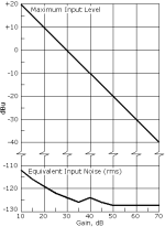
I have linked down below (if it works), a graph,from Gordon M6 Preamp, to show how EIN evolves at different gain settings. As can be seen the EIN is worse at lower gain settings and higher gain does not negatively impact the EIN.
Indeed it's even worse, Sound Devices specs uses A- weighting while ThatMicPre EIN specification is unweighted.
(Copy-pasted definition) "A-weighting is an adjustment applied to sound measurement to reflect how a noise is perceived by the human ear."
It can improve the measurement by up to 6 dB even though it's frequently about 2 to 4 dB.
If possible it would be great to have an A-wtd measurement of ThatMicPre EIN to be able to compare better.
Btw Sound Devices mentions -130dBV which actually is equal to -127,79 dBU (small detail).
I have linked down below (if it works), a graph,from Gordon M6 Preamp, to show how EIN evolves at different gain settings. As can be seen the EIN is worse at lower gain settings and higher gain does not negatively impact the EIN.
Attachments
Hi Xioran, Sorry but I'm not interested in doing that work. There are other good preamps out there that are designed for bipolar power supplies, some of which was mentioned by Azrod23 in post #82.Hello, OJG, this phone is single-end power supply instead of DC-DC plus and minus voltage power supply. Could you please change the open source circuit of GITHUB to the version of plus and minus voltage power supply?
Thanks, Azrod23 for answering Vpp with my exact thoughts.
As for comparing un-wtd vs A-wtd measurements, when the noise spectrum is flat, i.e. white, the difference between a A-wtd and un-wtd measurement in 20kHz bandwidth is about 2 dB. So the Thatmicpre would measure at roughly -130 dBu EIN at 60dB gain if A-weighted, which is quite a bit better than the MixPre spec. (The MixPre is much more than a preamp though so the comparison isn't quite fair).
You could configure Thatmicpre for 76dB gain by changing the gain resistor network values, but THD and bandwidth would start to suffer at such a high gain in a single stage. Better to use two Thatmicpre chained together
")
Hello @Azrod23 ,
Hello @ojg ,
Appreciate your insights and clarifications of nuances. I love data very much and I agree that marketing slides tend to twist the unit of measurement to give the spec a more glossy look (e.g. Rode occasionally [*] uses dBV instead of dBu for EIN, likely b/c this implies a higher absolute value, i.e. -131.5 dbV = -129.3 dBu [**]). As you have suggested, A- weighting (or lack thereof) is another aspect to take into consideration.
In the end, what I personally care about is having less noise in my recordings. I have recently contrasted a MixPre 6 II @ 55 db Gain with UMC202HD @ 51 db (max) Gain (both with a dummy 150 Ohm XLR plug) and I was hugely surprised [***] that, for frequencies > 200 Hz, MixPre appears to be 15-20 dB quieter than UMC202HD.
Would it be possible to somehow get the wav recordings of ThatMicPre using a dummy 150 Ohm Mic at e.g. 50/55/60 db (common values) of Gain, using a relatively high quality ADC? If so, that would allow an easy and objective noise performance comparison to any audio interface of interest on the market (at the same 50/55/60 db gain setting).
Regardless, thanks for your helpful and friendly feedback.
[*] https://rode.com/en/interfaces-and-mixers/rodecaster-series/rodecaster-pro-ii
[**] https://www.analog.com/en/design-center/interactive-design-tools/dbconvert.html
[***] https://drive.google.com/drive/folders/10KBZjUUdbQV9DZ0s9-JC87MS7Mf0FLWo
Last edited:
Could the significantly lower noisefloor of the MixPre be due to the floating point recording capabilities? The floating point capabilities indicates that they are doing tricks with the preamp gain and digital gain depending on the signal level and/or using a multichannel ADC with different preamp gains on each channel and then switching between those channels in software based on signal level.
So it would be more interesting to see what is the noise floor in the presence of a signal, i.e. the dynamic range. Typically done by looking at THD+N of a signal sweep from 0dBFS to say -120dBFS.
So it would be more interesting to see what is the noise floor in the presence of a signal, i.e. the dynamic range. Typically done by looking at THD+N of a signal sweep from 0dBFS to say -120dBFS.
Hey, ojg
Thank you for sharing this impressive project. The level of completion is really high, especially with the two options of desktop version and rack version. and the panels with precise dimensions. It's fantastic!
All the parts I ordered finally arrived yesterday, and I've completed my two rack version preamps. They're working perfectly.


Thanks again for the share, ojg!

Thank you for sharing this impressive project. The level of completion is really high, especially with the two options of desktop version and rack version. and the panels with precise dimensions. It's fantastic!
All the parts I ordered finally arrived yesterday, and I've completed my two rack version preamps. They're working perfectly.
Thanks again for the share, ojg!
Hi, ojg
That's right, the enclosure I'm using is not Hammond's. The only enclosure I can find here that is close to Hammond's size is the zs-8145 used by fanf2018.
It has the same external dimensions as Hammond's enclosure, but the internal dimensions are slightly different, particularly the PCB mounting slot is slightly higher, and the hole position for panel mounting screws is also different.
So, I redraw the panel PCB to fit this enclosure.
The first one, DIY kits for self-assembly.With built kits, do you mean kits with the PCB and all the parts including the enclosure where the buyer would do the soldering and assembly, or do you mean finished units ready to plug and play?
Hi OJG, thanks for this work! I just built one rack version, and everything works well, but the potentiometer can not work on it, meaning there is no gain control. How can I figure it out? Thanks!Project page on Github
A simple, high-quality DIY microphone pre-amplifier with switched gain.
The background for this project was that I needed a simple but good microphone preamp for doing acoustic measurements. I needed a switched gain to be able to reproduce the gain setting in a more predictable way than what is possible with a potmeter. I could not find any existing DIY designs, so I decided to make one.
The design is based on the excellent THAT1510 preamp IC. It is also compatible with SSM2019 or INA217. I have followed all THAT's datasheets and app-notes to implement a robust, best-practice design.
A goal was to use simple through-hole parts that I and other DIYers usually have in our parts drawer. So there are no additional IC's or voltage regulators for example, it just uses simple transistors, capacitors and zener diodes for supply filtering and regulation. I selected affordable switches and connectors to keep cost down. Many parts can be substituted without sacrificing performance.
This is an open-source project released under CC-BY-SA-4.0 license. It basically means you can use it as you want as long as you share modifications under the same license, and attribute back to this project. See LICENSE.txt for details.
Specifications
-----
* (Will operate with lower voltage DC power supplies with reduced phantom voltage and max output level).
- Microphone preamplifier with switched gain and 48V phantom power.
- XLR input and output connectors.
- Phantom power on/off switch.
- Phase invert switch.
- Gains (dB): 0, 10, 15, 20, 25, 30, 35, 40, 45, 50, 55, 60.
- Gain deviation from nominal: Max +/-0.5dB using E12-series resistors.
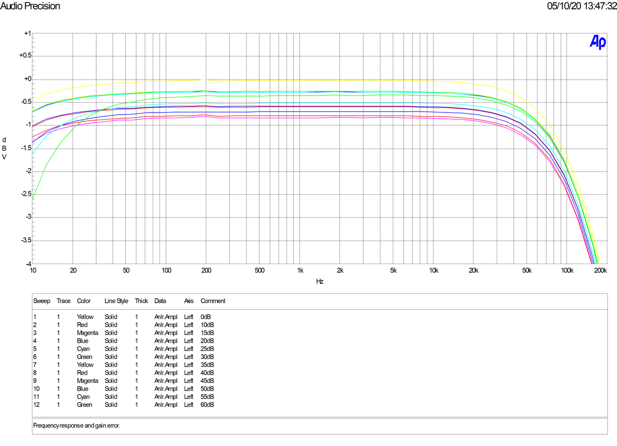
- Frequency response: 0/-3dB from 10Hz to 100kHz for all gain settings.
- Impedance balanced output.
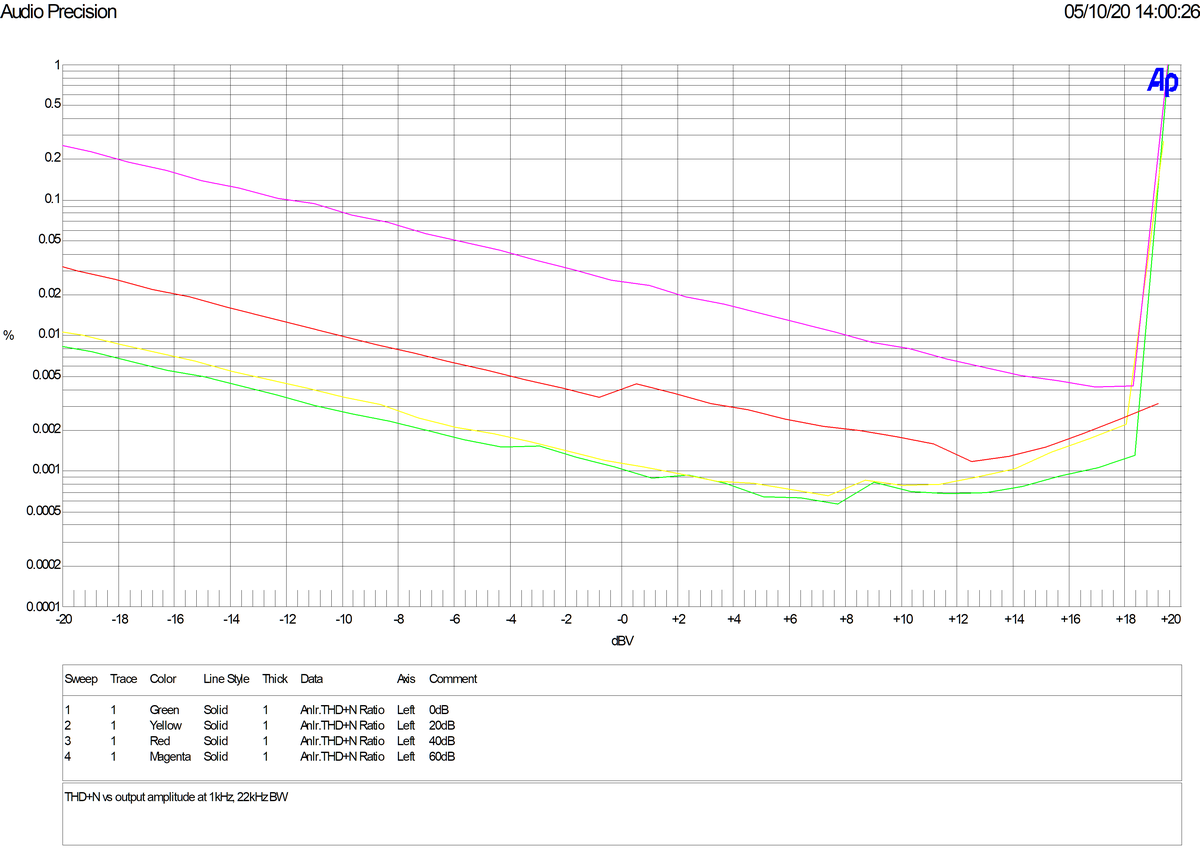
- Max output level: 20dBu at 0.1% THD (1kHz).
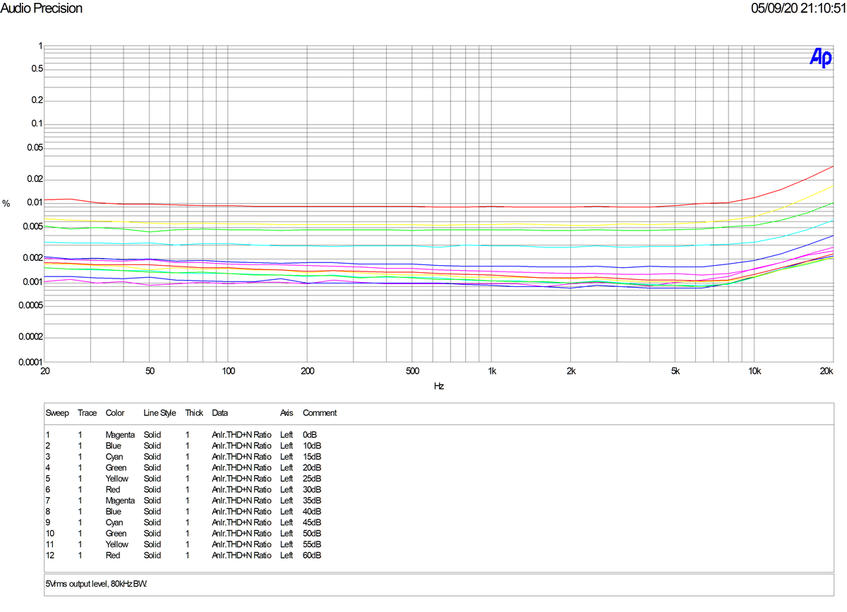
- THD+N less than 0.005% at 1kHz at 18dBu output level for all gain settings (20-20kHz BW).
- 48V DC power supply required, 30mA max.
* PCB dimensions 75mm x 120mm, fits the Hammond 1455K120x(1455K1201 - Hammond Mfg.) enclosure.
* Gain switch on top of enclosure for easy access.
Schematic
-----
View attachment 1163289
Desktop version:
-----
View attachment 1163290
Rack version:
-----
View attachment 1163291
View attachment 1163294
Measurements
-----
### Output noise vs gain
20-22kHz BW un-wtd, 150ohm source impedance
| Gain(dB) | Output Noise (dBu) | EIN (dBu) |
| --- | --- | --- |
| 0 | -98.5 | -98.5 |
| 10 | -98.2 | -108.2 |
| 15 | -97.8 | -112.8 |
| 20 | -96.8 | -116.8 |
| 25 | -95.6 | -120.6 |
| 30 | -93.2 | -123.2 |
| 35 | -89.8 | -124.8 |
| 40 | -86.8 | -126.8 |
| 45 | -82.6 | -127.6 |
| 50 | -77.8 | -127.8 |
| 55 | -73.1 | -128.1 |
| 60 | -68.3 | -128.3 |
### Frequency Response
### THD+N vs Frequency
### THD+N vs Amplitude
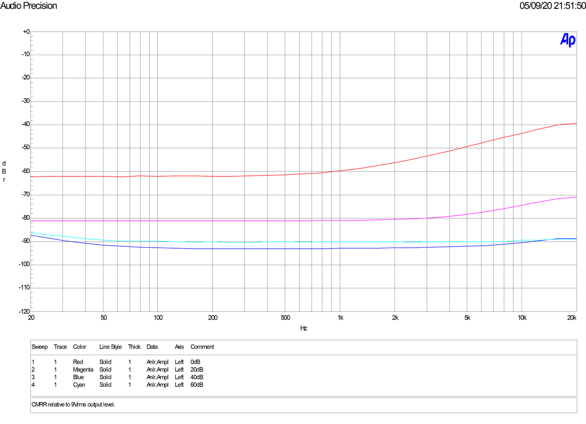
### Common Mode Rejection Ratio
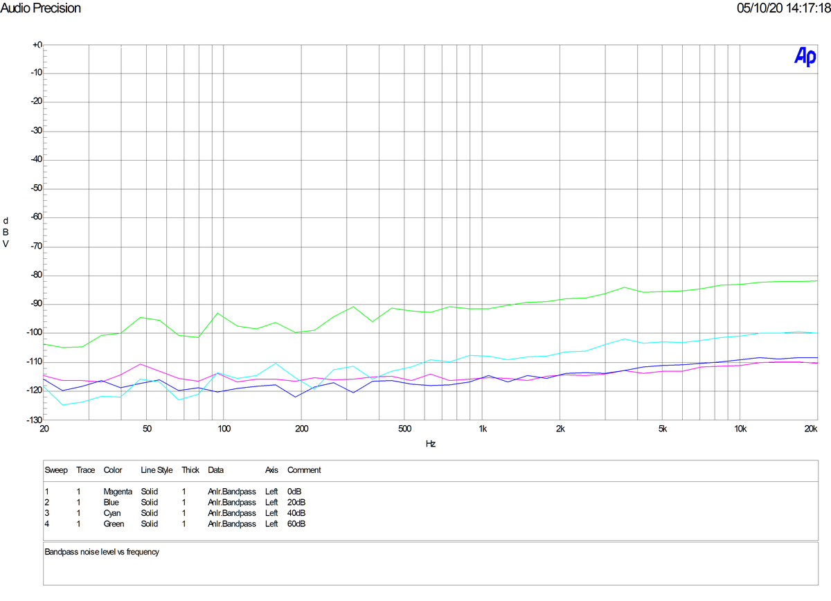
### Bandpass Noise Level
Note no measureable hum.
---
OJG 2020
Hi Hwasonglim, thank you, glad you wanted to try build one.
You are not giving us much info to help you with troubleshooting. Have you connected the front board with the gain switch and resistors to the main board properly? Some pictures of your assembled boards might help us help you.
You are not giving us much info to help you with troubleshooting. Have you connected the front board with the gain switch and resistors to the main board properly? Some pictures of your assembled boards might help us help you.
Hi, Thank you for replying, I just found out, that there is no problem on board, the gain header has the correct resistor values output.
But the key is that I bought the fake chip, and the pin1 and pin8 couldn't read the changes of the RG. So the gain changing fails.
Now I just replaced the genuine chip, and it works well. BTW, there are lots of fake 1510/1512 outside.
I put two PCBs into one rack as a NEVE-style dual-channel pre-amp.
Thank you for this design!
- Home
- Design & Build
- Equipment & Tools
- ThatMicPre - an open-source mic preamp