Hi Djim,
I found that some drivers don't like to have any L12 (Hornresp S1=S2 L12=.01cm), and others need a L12 section to smoothen the first big dip in the TH response. In your drawing (Post #783) you are showing short "stubs" left and right, so you would have to account for these. The other way is a throat chamber with a controlled opening that equals the throat cross-section.
This is only based on Hornresp simulations.
Regards,
Hi NEO Dan,
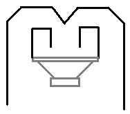
Yes, I have been guilty of drawing a few of those. I have now convinced myself, that going with a more "squarish" throat might be better, also, it might help to extend the first section from the throat all the way to the back of the enclosure, and then expand left and right from there. You could make the case that loading against a flat sheet might be a good way to go. Ultimately, we have to build and test.
Regards,
Last edited:
Hi Oliver,
The 'stubs' (don't know the word) as you call them are the S1-S2 section (compliance volume). The length of them is only important for the high end of the bandpass, the volume can lower the first system resonance slightly. Adding a chamber instead is indeed different and could be a solution for getting a smaller total volume but at cost of extra compression losses.
No need to worry ; it works in the real world…
Hi Djim,
I guess I was borrowing the term for a short waveguide section, which is called a "stub" (e.g.: 1/4 wave stub). Maybe you could alternately model this by integrating the total volume of the stubs/cone/chamber in front of the throat, and call it a throat chamber; particularly at the wavelength involved. It's nice to know that it "...works in the real world...".
Regards,
Thanks CRESCENDO for the quick response.
So what is the clipping power of the QSC PLX3402 into a 4 ohm load, according to the manual/technical specifications?
I was curious, so I checked a spare PLX3402 I have.
These tests were done under zero load (no speakers or speaker cable connected). I measured the resistance at the speaker terminals at the rear of the amp for some reason. It fluctuated between 5.2 and 7ohms. Maybe un-useful info, but thought I'd share anyway.
Clip limiter OFF
40 Hz test tone
Enough level to drive hard into clipping
109.7v
Clip limiter ON (how my cab was measured)
40 Hz test tone
Same setting as above
94.6v
So, we can clearly see my driver never saw anywhere close to the 2200W spec during testing. I didn't drive it that hard into the clip limit light either. Soon I'll test the output of my TH-18 with the broken in driver and hopefully my voltmeter will be able to record the voltage this time
")
*Note: I could drive more level to the amp to gain a little more voltage (~130dB with a 100Hz warble tone), but this is just to gauge the affect of the clip limiter. Driving the voltage harder than above would've pushed it further from testing conditions in question anyway.
Hi,
If you built a steel angle frame around the opening would that stop most of the flexing at the mouth,I was thinking around the outside of the box,could also weld the grill to it.
Thanks,
NS
Hi All
3 screen prints showing the TH 18 being blown apart with internal pressure on the panels
First without no ties
Second with 2 ties as Djims suggestion
Third with 2 ties and some double material added to the speaker base.
The pressure is consistent for all 3 sims the telling parameter is the scaling factor used. The last sim shows deformation of less than one third of the first.
If you built a steel angle frame around the opening would that stop most of the flexing at the mouth,I was thinking around the outside of the box,could also weld the grill to it.
Thanks,
NS
ooppss,I see it has been done in post 200,lol.At least a good idea,
I have 2 B&C18PZB100 on theUPS truck,and I am presently reading this whole thread,so May I ask if the plans at #6 are the ones to use or is a upgrade here,I'd like to start getting supplies together,
Thanks,
I have 2 B&C18PZB100 on theUPS truck,and I am presently reading this whole thread,so May I ask if the plans at #6 are the ones to use or is a upgrade here,I'd like to start getting supplies together,
Thanks,
hi NEO Dan,
I don't think my head would fit in that box,lol.
Yea for thinking outside the box
I don't think my head would fit in that box,lol.
yep,your right as rain,boy
Everything is better or bigger in TEXAS,We have some of the most friendliest people in the world here.
Wow, there must be some truth to the whole "everything's bigger in Texas"...
Everything is better or bigger in TEXAS,We have some of the most friendliest people in the world here.
Everything is better or bigger in TEXAS,We have some of the most friendliest people in the world here.
We don't suck too bad over here in Cali either
Hi Cali,We don't suck too bad over here in Cali either
I going to make the BA festival this year in San Francisco,Looking forward to it,
Going to tour the area while I'm there,I like to shoot pictures ,would like to try a few restaurants and wineries,
- Home
- Loudspeakers
- Subwoofers
- TH-18 Flat to 35hz! (Xoc1's design)