Regarding cone correction, I always wonder why people don't include the thickness of wood times the speaker's mounting diameter in their HR inputs.
I do, I make a cad model of the cone and surround and baffle thickness and measure the volume to be used in my models
one of my early ones in sketchup format B&C 18SW115 w/18mm baffle
Sorry Dan, but the formula only uses the "Thrust" factor and is therefore not accurate in my view. The motor force (BL) needs to be divided by the total product of resistance. In other words, you also need the resistance as result of acoustic suspension losses and the mechanical suspension losses (= Res).Adding to the list
18PZB100-8 112.48
I am only not sure yet if Res should be added as a serial resistance or parallel resistance to Re.
Good to see this thread back on track ")
On the topic of cone correction... Reading back to martins post, he is working on it but it may end up very similar to the DSL 118. How would things work if indeed the corrected version was a very close clone of that sub? I dont think we want to step on Mr. Danleys toes, considering how helpful he has been this community. Maybe we should ask him to weigh in?
I'm making 4 of these starting tomorrow so I'd be interested on how to sqeeze the most performance possible
Sorry Dan, but the formula only uses the "Thrust" factor and is therefore not accurate in my view. The motor force (BL) needs to be divided by the total product of resistance. In other words, you also need the resistance as result of acoustic suspension losses and the mechanical suspension losses (= Res).
I am only not sure yet if Res should be added as a serial resistance or parallel resistance to Re.
OK Djim,
If the resistance is a missing load on the system then it should be additive/series. How is Res calculated?
Interesting results via Re+ResHi Dan,
Well, I found: (Bl*Bl) / Rms, but than the Res seems to become too big of an influence.... Have to dive in it.
15TBX100 606.37
18SW115 490.71
18SW100 398.93
18PZB100 664.26
15SW100 551.79
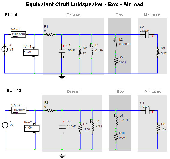
Keele's AES paper ("Comparison of Direct-Radiator Loudspeaker System Nominal Power Efficiency vs. True Efficiency with High-BL drivers") contains an Equivalent Circuit of two similar drivers.
One driver has a BL of 4 and the other a BL of 40. You can clearly see that the value of R2 (value 70) increases immensely compared to R7 (value 1750). Of course it should be noticed that we are dealing with a sealed enclosure but it seems to confirm that high BL drivers have a dominant mechanical resistance (R7 that represents Res) over Re (represented by R6).
Anyone who likes to comment?
Hi.Interesting results via Re+Res
15TBX100 606.37
18SW115 490.71
18SW100 398.93
18PZB100 664.26
15SW100 551.79
In My initial design I simmed with the Precision Devices PD1850.
This gave a lower efficiency which I hoped would be compensated for by less compression at war volume. It also gave a deeper frequency response.
I would be interested to see how this driver compares with the above.
Would give more details but am posting this from My hospital bed

Regards Martin (xoc1)
I wish you'll be out o there.
Martin, thank you for your time and sharing with us your knowledge and results.
We all wish you recovery ASAP.
Sergey.
Hi.
In My initial design I simmed with the Precision Devices PD1850.
This gave a lower efficiency which I hoped would be compensated for by less compression at war volume. It also gave a deeper frequency response.
I would be interested to see how this driver compares with the above.
Would give more details but am posting this from My hospital bed
Regards Martin (xoc1)
Martin, thank you for your time and sharing with us your knowledge and results.
We all wish you recovery ASAP.
Sergey.
hope its not to serius m8.Hi.
I would be interested to see how this driver compares with the above.
Would give more details but am posting this from My hospital bed
Regards Martin (xoc1)
get well soon.
I think that the best way to apply the cone correction is to account for the cone volume and the baffle. The added areas can then be used with a simplistic Hornresp sim. Looking at the Danley designs the baffle is quite thick and the cone correction touches down to the baffle area. This implies that the baffle used is thick enough to accommodate the x_mech of the driver.I do, I make a cad model of the cone and surround and baffle thickness and measure the volume to be used in my models
one of my early ones in sketchup format B&C 18SW115 w/18mm baffle
The thickening of the baffle is something that we have already explored with the fitting of a packing ring to increase the driver clearance. Of course it is easy to implement a different material thickness in a production product, but not so easy for the DIY'er who needs a decent yield from their sheet stock.
For a DIYdesign it may be an advantage to just go with the 18mm baffle even if this does not give such a good shape for the horn at the S2 point.
The methodology I am thinking of for implementing the cone correction is to work out a method that can be used by any DIY builder on any offset style TH horn.
This will probably result in a less extreme throat correction than in the Danley TH118. To clone this without any technical explanation or justification would be totally wrong in my opinion.
Regards Martin (Xoc1)
Hi Martin (Xoc1) or Tom Danley (or anyone who wants to respond):
I have asked this a number of times, but have not been getting an answer from any of the experts: "why not use a throat chamber large enough to accomodate the motion of the driver plus whatever Hornresp/AkAbak tells us is optimum, and couple from there into the horn with an opening the size of S2?" Shouldn't a properly sized chamber load the driver more evenly? The shape of the opening could be changed to optimize flow characteristics. This would allow for easy manipulation of the horn parameters including the S1/S2 area. It might make it easier to manipulate the horn for different drivers. Basically, all the wood is already there for baffles and stand-off rings.
And second: "While the throat area in any horn design gets a lot of attention, should we not be watchful of what happens on the other side?" The motor/basket/cone blocks a lot of the horn duct, and the coupling to the mouth does not seem to be handled very cleanly in a lot of these designs.
I don't have your obvious experience nor the facilities to build and test multiple models, that's why I'm asking. I'm not asking for someone to design a TH, but just about the general design considerations.
Regards,
This will probably result in a less extreme throat correction than in the Danley TH118.
I think you are referring to the compression plate / cone correction. right?
A compression plate doesn't have to have it's opening in the middle, just has to have a smaller opening than the Sd of the driver.
hi oliver .
i agree a throat chamber solves many problems.
the only drawback i can see ,is a dip is intoduced above ~100hz(in a 35~40 hz th.
not a problem when used only as a sub.
the mouth isnt so much an isu because the pressure being less(generaly)
thats just my 2 cents
i agree a throat chamber solves many problems.
the only drawback i can see ,is a dip is intoduced above ~100hz(in a 35~40 hz th.
not a problem when used only as a sub.
the mouth isnt so much an isu because the pressure being less(generaly)
thats just my 2 cents
I think you are referring to the compression plate / cone correction. right?
A compression plate doesn't have to have it's opening in the middle, just has to have a smaller opening than the Sd of the driver.
Hi Jbell the V shape throat correction is the full width of the cabinet.
This is what makes it suitable for extending the middle fold in the SS15 / TH18 layout. The closer the V shape to the driver the longer path length that can be accommodated.
No visual examples as I am still typing this at the terminal at my hospital bed. At least I should be going home within an hour or so.
PD1850 716.9Interesting results via Re+Res
15TBX100 606.37
18SW115 490.71
18SW100 398.93
18PZB100 664.26
15SW100 551.79
Hi.
In My initial design I simmed with the Precision Devices PD1850.
This gave a lower efficiency which I hoped would be compensated for by less compression at war volume. It also gave a deeper frequency response.
I would be interested to see how this driver compares with the above.
Would give more details but am posting this from My hospital bed
Regards Martin (xoc1)

For a minute there I didn't think you were gonna make it... Glad you pulled through m8
- Home
- Loudspeakers
- Subwoofers
- TH-18 Flat to 35hz! (Xoc1's design)