Hi Samuel,
Your question is probably based on theoretical models instead of real world events. In the reality all enclosures and drivers suffer from system losses of all kinds:
A) Thermal Compression
B) Dynamic Compression (result of boundary effects, changing acoustic air properties ect)
C) Building errors (driver volume is not compensated in the S4 area, extra corner volume ect).
In reality basreflex do meet their predicted max level output (above a certain frequency) because the basreflex port starts to increase its stiffness (port compression) as power is increased. This is the result of the relative small bass-port. The effect is that the low end of the basreflex is less than predicted but the area above gains in level and does meet its predicted level. Often you will see the opposite in Tapped Horns and horns in general.
Is that only for undersized ports in a ported enclosure? Any Specific Mach speed where this occurs? What I mean is, is there some special port size that one would shoot for in a BR to minimize the LF loss, or does that happen even with very large ports as well?
Hi mRgSr,
All basreflex ports/vents suffer from compression one way or another. In Young’s study from 1975 about basreflex ports, he pointed out a maximum velocity of 10m/s for basreflex-ports. However, that’s only half the story. Port compression is determined by velocity and pressure. In other words the higher the SPL the lower the efficiency of the port.
But it doesn’t end with just basreflex ports. Some of you may have noticed I am not a huge fan of T-TQWT designs for PA (high level subs). It’s not that I question the qualities of a T-TQWT design but for all quarter wavelength resonators (horns, tapped horns and all equivalents) counts that squeezing them down in smaller than ideal enclosures, comes at costs that don’t show up in sims. Trying to design a quarter wavelength resonator in a relative small package for high level demands is much more a challenge than just a satisfying flat-response from a 'no-level' sim. Yes, 'no-level' and not 'low level' since the Thiele-Small parameters of a driver change as soon it starts moving and system losses are not even part in those sims.
There are signs all around. For instance, how many noticed the higher knee at the low end compared to its model? If you have followed this thread about the Xoc1-TH18 you can find several experiences with different drivers and different power levels. They all seem to end around 127dB average SPL levels. For Crescendo that is a plus since he was looking for authority at the low end and his drivers seem to be dealing well with the compression levels. From a designer perspective it should be a sign...
That's the point, the input doesn't pay out in output. To get near 130dB you loose the efficiency as result of compression factors. The 18SW115 or similar don't have + 3dB compression levels at their AES power ratings from their own...I know 127dB is not the limit, but then I've used a stronger driver and amp.
???As a summary judgement against quarterwave design
Can you provide an example of something that is not bound by the proposed limitations you previously mentioned? Is there any PA sub system you actually like?That's the point, the input doesn't pay out in output. To get near 130dB you loose the efficiency as result of compression factors. The 18SW115 or similar don't have + 3dB compression levels at their AES power ratings from their own...
???

I think driver selection and compression ratio among other factors in the overall schema are not balanced in many designs. But that is no reason to brand quarterwave systems as a flawed type IMO.
I have gone on to build other systems of similar efficiency and they behave as intended.
I think the TH115 has been around for quite a while, and the TH118 is a direct adaptation of that design. I don't know the history but I would guess the TH118 came about when a strong enough driver became available. Does anyone know if the TH115 was originally loaded with the 15TBX100? In looking at the layout of the TH115/TH118 the volume of air near the throat is much larger than what we are building...

Anyway if you look at the force per unit of cone area it breaks down like this:
15TBX100-8 149.12
18SW115-8 146.00 ~98%
18SW100-8 106.22 ~71%
So even though the SW100 series has great X var it may not be strong enough to push the load this enclosure presents.
Is there any PA sub system you actually like?
While I won't claim to speak on anyone's behalf... I think I understand the thinking. Any system that places emphasis on one attribute over another, at the expense of overall balance... is inherently non-optimized.
Bjorno's t-tqwp's are a great example. They gain extension, at the expense of other design parameters. In many cases this is an acceptable tradeoff. In PA... I don't believe it is.
Having a sub that runs out of power handling at the time it runs out of xmax, at the time it runs out of cone stiffness, at the time it starts bumping into various compression(s), as well as other things to balance -- is an optimized system.
That is the kind of system I personally appreciate. Others may disagree.
Dan,I think the TH115 has been around for quite a while, and the TH118 is a direct adaptation of that design. I don't know the history but I would guess the TH118 came about when a strong enough driver became available. Does anyone know if the TH115 was originally loaded with the 15TBX100? In looking at the layout of the TH115/TH118 the volume of air near the throat is much larger than what we are building...
Anyway if you look at the force per unit of cone area it breaks down like this:
15TBX100-8 149.12
18SW115-8 146.00 ~98%
18SW100-8 106.22 ~71%
So even though the SW100 series has great X var it may not be strong enough to push the load this enclosure presents.
The DSL TH-115 has been loaded with the B&C 15TBX100, typically fitted with the 4 ohm version now, 8 ohm when introduced.
The 18SW115-4 was adopted in the TH-118 after using the 18 sound NLW9600, both had the BL and stiff cones needed for TH use with a larger cone.
DSL tried the B&C 15SW115-4 in the TH-115, here are Tom Danley's comments:
"We just measured the B&C 15SW115-4 in a TH115. I was hoping for an “upgrade” version.
Over most of the freq range it is about 2dB lower than the standard driver we use. It was equal around 100hz and right around 40Hz (for maybe 5 cycles) wide it was about 2 dB louder. Below 40Hz it dropped 6dB or more down to 30Hz."
Tom did not mention how it fared with higher input levels, I expect at high power the 15SW115-4 could outpace the 15TBX100-4 by a small margin, but the driver and amp expense make it not worth the investment for most.
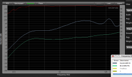
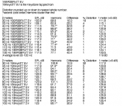
In my comparison of a BR cabinet loaded with a B&C 18SW115-4 using a large port, (7.25 x7.25 x 9.75 deep with a 13.25 diameter inside circle) which matched the Keystone TH’s LF corner pretty closely, I found that the BR lost LF relative to HF in the high power (77.5 volt) sine wave tests compared to the pink noise Magnitude Response tests done at several watts, probably due to port compression.
At 40 Hz, the Keystone is +9 over the BR using sine wave, but only 5 dB difference at lower power pink noise, a 4 dB loss due to port compression.
Conversely, at 100 Hz, the sine wave test has the BR only 3.4 dB less than the Keystone, while the low power pink noise is +8.5 dB, the Keystone “flattens out” in the upper range by 5.1 dB at high power.
It could be argued that the BR port compression allows the cabinet to sound more punchy at full tilt boogie, as our ears need less bass at loud volumes to perceive it as equal in level compared to at low level.
One certainty in TH usage is that there is far more stress on the cone when reaching Xmax compared to a BR, lighter cones such as the Eminence 4015Lf (or even lighter 3015LF) that work fine in a BR tend to fold up, distort, and put out less than predicted when loaded in a TH at power levels capable of reaching Xmax.
Art Welter
Attachments
Last edited:
Anyway if you look at the force per unit of cone area
How does one calculate this?
it breaks down like this:
15TBX100-8 149.12
18SW115-8 146.00 ~98%
18SW100-8 106.22 ~71%
What percent is the TBX driver?
All TH’s and traditional horns with relative high compression at the driver tend to compress the output at the higher part of the bandwidth (roughly at and above their 3/4 resonance), at high levels. That’s why I wrote that it is often the opposite of basreflex where port compression is concentrated around the tuning of the port, at high levels.
When a 'weaker' driver is used it will not reach its targeted average output level as result of the relative high compression ratio of the horn. Using a cone volume correction does not increase the average output level but increases the compression. At the low end it usually restores the output difference between model and measurement with approximate 1 to 2dB. For 'weaker' drivers the increasing compression ratio can become an issue. In order to increase SPL levels above (roughly) 3/4 resonance you need to lower the compression ratio of the horn/pipe by increasing its diameter.
For Tapped Horns you want to achieve that the highest pressure point/zone is located above the centre of the driver to obtain the most equal distribution of the forces on the cone. You can use cone correction plus an additional constriction at S2 to make that happen. This will turn the first section (S1-S2) into a compliance volume. The throat 'sees' this compliance volume as a parallel section to the horn. It will lower the first system resonance and can be used to 'tune' the system a little. If I am correct it works like a kind of 'ballun' for antenna’s.
When the section S2 to S1 narrows the high pressure point/zone tends to shift backwards. If that is the case section S1-S2 changes from a compliance volume into part of the horn. This happens in many commercial designs on purpose to obtain the longest horn-path possible but at the costs of less equal distribution of the forces. To overcome that problem they usually locate the driver further upwards in the horn (towards the mouth) to lower the compression ratio at the position of the driver.
Many TH’s tend to have their driver closely towards S1. The result is high compression ratios and the highest pressure point/zone located near one edge of the cone. That’s why 'weak' cones tend to fold at certain frequencies since the high compression ratio prevents the cone from moving linear. To insure the pressure point stays above the centre of the driver and keep forces equally distributed you need to keep section S2 to S1 straight or (preferably) give it an expansion towards S1.
Another way of dealing with correct positioning of the pressure zone is to use the 'Symmetric' Tapped Horn with multiple horn/pipe tunnels. Especially for 'weaker' drivers this is a good solution as forces are symmetrically distributed over the cone. It is important to start the horn large enough to keep the compression as low as possible.
Last edited:
How does one calculate this?
What percent is the TBX driver?
Hi Justin,
BL²/Re is the force component then I divide that by the Sd*.001 to arrive at the figures shown. This could be expanded on with other variables to allow driver matching across a range of different TH's.
The TBX represents the full 100% value.
Hi Justin,
BL²/Re is the force component then I divide that by the Sd*.001 to arrive at the figures shown.
This is quite interesting.
This could be expanded on with other variables to allow driver matching across a range of different TH's.
Do you have examples to share and/or ideas/suggestions you've learned?
I would assume one would want a driver with enough force to push the load an enclosure presents, but not too much as to damage the driver. Is this balance point found only by trial and error?
At this point yes...
Using the "math" above as part of the selection process I chose a 15" driver to try in my TH18 variant and it behaved very much as expected, I was able to reach the driver limits with the amount of power I expected but I wanted a bit more cone control. From there I was able to extrapolate what I could manipulate to get more performance from that driver and the selected amplifier. The resulting new TH allows for the amp to be driven ~3-6dB into clip without physical distress but still get beyond the driver x var. The happy situation jbell described of getting all the driver has to offer and still squeezing out all the performance you can. That 8Ω 15" TH is as voltage sensitive as my 18SW115-4 TH18 variant >46Hz and below will fill in nicely with the other three cabs the amp can run.
Have you noticed any difference in LF response between 1 and 2 cabs, have you laid them down butted mouth to mouth?
Are you somehow measuring the driver's excursion to find out it's exceeding it's Xvar?
How different is your TH18 than Xoc1's? Just adapted for your driver you chose or various different techniques? Do you know how the driver you chose performs in Xoc1's TH? I know there are different drivers w/greater force per area, but they have less xmax than the SW - in the back of my mind I felt the SW may sound cleaner by staying further away from xvar & xlim than the driver w/more force & less xvar & xlim.
I have yet to measure 1 cab vs 2 cabs, if that's what you're asking.
You have a PM
Yes.
I swapped some models with Martin. I chose to incorporate cone correction and a different expansion. I also built two versions, the second was 2dB stronger on the low end and more restrictive due to the .5 higher CR but both had the same FB, I preferred the first.
Knowing what your reasoning was - what do you think now about how they perform? I would guess you run out of amp way sooner than you had anticipated and they struggle below 40 as the load increases toward FB? Everything does, but the lower Q more massive and powerful drivers fare better at driving FB. Ideally FB would be more out of band like the 28Hz DSL was claiming, but they pulled the impedance plot from the pdf even though they decided to stick with the 18SW115...
No I meant listening, give yourself a brake from production/spinning and go down range for a listen The difference in LF directivity and apparent LF power should be noticeable at a distance. Illmerica, Undertaker, and Some Chords are pretty strong.
Yes.
I swapped some models with Martin. I chose to incorporate cone correction and a different expansion. I also built two versions, the second was 2dB stronger on the low end and more restrictive due to the .5 higher CR but both had the same FB, I preferred the first.
Knowing what your reasoning was - what do you think now about how they perform? I would guess you run out of amp way sooner than you had anticipated and they struggle below 40 as the load increases toward FB? Everything does, but the lower Q more massive and powerful drivers fare better at driving FB. Ideally FB would be more out of band like the 28Hz DSL was claiming, but they pulled the impedance plot from the pdf even though they decided to stick with the 18SW115...
No I meant listening, give yourself a brake from production/spinning and go down range for a listen
The difference in LF directivity and apparent LF power should be noticeable at a distance. Illmerica, Undertaker, and Some Chords are pretty strong.PM replied.
Ah, ok. Nice.
I think they perform quite well. The first night one was in use, it had 2200W available and didn't sound stressed one bit. I was surprised how much authority they had still with a 25Hz test tone. Perhaps they *could* use more power, but I'm still not sure a driver with more force & less xmax would sound any better. And some suggested the 18SW115 (more force and more xmax) might not get any louder than the SW100 or 18LW2400 since they're less sensitive in this enclosure (IIRC) and need a ton of voltage to reach xmax (after compression is factored in). I'd really like to try tho but, they don't grow on trees like birch does ;P
Yeah, we've played with positioning and configuration. Two TH-18 is a big difference from just one. And, so far, we enjoy stacking one on top of the other on their side - puts their "force" more at chest level, which all the bassheads enjoy. Turntable rumble (for those who choose to play real vinyl at our nights) is still to be completely removed (no, we don't have a concrete floor or DJ booth) - but that's a totally different story
Once I have 4, they'll be stacked and butted up, mouth to mouth. I can't wait for a center stack of 3x3. I'd like to somehow make sure I've made the right driver decision first. I'm hoping these conversations will help.
Ah, ok. Nice.
I think they perform quite well. The first night one was in use, it had 2200W available and didn't sound stressed one bit. I was surprised how much authority they had still with a 25Hz test tone. Perhaps they *could* use more power, but I'm still not sure a driver with more force & less xmax would sound any better. And some suggested the 18SW115 (more force and more xmax) might not get any louder than the SW100 or 18LW2400 since they're less sensitive in this enclosure (IIRC) and need a ton of voltage to reach xmax (after compression is factored in). I'd really like to try tho
but, they don't grow on trees like birch does ;PYeah, we've played with positioning and configuration. Two TH-18 is a big difference from just one. And, so far, we enjoy stacking one on top of the other on their side - puts their "force" more at chest level, which all the bassheads enjoy. Turntable rumble (for those who choose to play real vinyl at our nights) is still to be completely removed (no, we don't have a concrete floor or DJ booth) - but that's a totally different story
Once I have 4, they'll be stacked and butted up, mouth to mouth. I can't wait for a center stack of 3x3. I'd like to somehow make sure I've made the right driver decision first. I'm hoping these conversations will help.
Last edited:
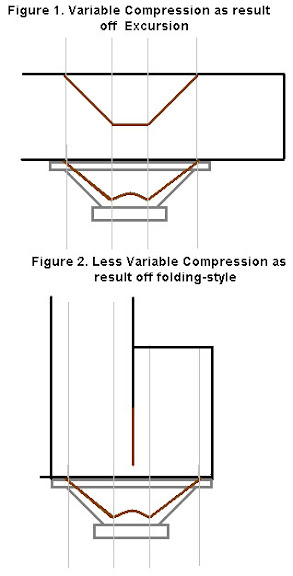
Variable Compression as result of folding style:
Variable Compression as result of folding style:
When the traditional horizontal folding-style is used (figure 1.), the compression at the driver changes as result of the excursion. When the Cone moves inwards (into the horn) the distance to the opposite baffle becomes smaller (more compression). When the Cone moves outwards the distance to the opposite baffle becomes larger (less compression). The result is that the high-pressure zone tends to move from the centre towards one edge of the driver. This mechanism makes the Compression ratio variable and decreases linear movement.
When you change the traditional folding style into a vertical aligned folding-style (figure 2.),
the compression ratio only changes locally at the centre of the driver. Also, a vertical aligned folding-style allows higher compression ratio’s to be used to insure no movement of the high-pressure zone. This will improve linear movement.
- Home
- Loudspeakers
- Subwoofers
- TH-18 Flat to 35hz! (Xoc1's design)