Consequently, a fixed input voltage makes sense for sensitivity comparison between different drivers, as well as different enclosures.
Hi Oliver,
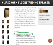
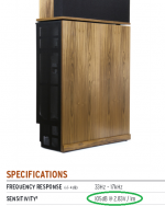
It seems that even Klipsch can't decide which way to go
") .
.105 dB @ 1W / 1m in one place (see Attachment 1)
105 dB @ 2.83V / 1m in another (see Attachment 2)
Kind regards,
David
Attachments
If it is not too much trouble, Re + complex AC reactance, for a 1W/1m simulation.
Hi Djim,
I don't understand
.Isn't Re + complex AC reactance already given by the electrical impedance chart, and how does this relate to a 1W / 1m simulation, where a value of Eg equivalent to 1W into Re is being used?
Kind regards,
David
Thanks again Oliver.
One more question and related to build. I've seeing people using screw over nail working with polywood, Is there any specific reason? If it was different wood like MDF the reason is clear once it's compatible with nail.
One more question and related to build. I've seeing people using screw over nail working with polywood, Is there any specific reason? If it was different wood like MDF the reason is clear once it's compatible with nail.
An externally hosted image should be here but it was not working when we last tested it.
To use removable perforated (or extruded) metal grill is necessary to change a little one panel shape adding material as highlight in red. So it creates a parallel surface with bottom panel.
An externally hosted image should be here but it was not working when we last tested it.
An externally hosted image should be here but it was not working when we last tested it.
An externally hosted image should be here but it was not working when we last tested it.
Last edited:
Hi LORDSANSUI,
I used to only use screws, but since I've gotten a number of air nailers for other construction projects I've come to realize that nails do a fine job too.
The difference is in the clamping force, with screws at 8" intervals you will not need clamps, with nails at even smaller intervals you may still need to clamp, and you may need more drying time for the glue.
Most guys that put a lot of boxes together in the diy community recommend polyurethane glue, e.g.: Loctite PL Premium; and nails. I have had good luck with regular "yellow" carpenter glues, e.g.: Titebond Original; with nails and with screws. Both glues are widely available, e.g.: Home Depot. PL will do a better job bridging small gaps, but for horn construction you don't want "small" gaps, oh well. I like to pretreat edges with a wipe of carpenter glue, and let it soak in, then reapply glue prior to putting the wood pieces together.
Also, take a look here: Danley DTS-10 "Super Spud" DIY kit - AVS Forum | Home Theater Discussions And Reviews The grooving of the side panels to accept dividers and braces is the best way to go about it, but quite time intensive to do by hand. It makes a lot of sense for enclosures that are being carried about, dropped out of trucks and generally mishandled. Horns have a lot of acoustic pressure changes, especially in the throat area.
I'm sure you'll develop your own techniques.
Regards,
Hi David,
Post #81: "... seems that even Klipsch can't decide which way to go..."
I'm sure there is one point in the frequency response where both are correct, or maybe not?
Industry has been quite willing to hide reality in a cloud of standards, to quote Andrew Tannenbaum: "The nice thing about standards is that you have so many to choose from. ( https://en.wikiquote.org/wiki/Andrew_S._Tanenbaum )
Regards,
Hi David,I don't understand
Isn't Re + complex AC reactance already given by the electrical impedance chart, and how does this relate to a 1W / 1m simulation, where a value of Eg equivalent to 1W into Re is being used?Kind regards
I meant Re + the resistance from complex AC reactance, aka Zmin.
I'll send you a more detailed message since it is perhaps too much off-topic.
Regards,
Djim
I'm sure there is one point in the frequency response where both are correct, or maybe not?
Hi Oliver,
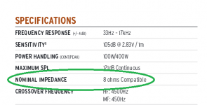
Klipsch gives the nominal impedance as "8 ohms Compatible", so I guess the 1W / 1m input voltage is calculated assuming an 8 ohm load, meaning that:
105 dB @ 1W / 1m
105 dB @ 2.83V / 1m
are one and the same, for this case at least
.Kind regards,
David
Attachments
Let me back at one subject again, unfold process and advanced centerline method. I became little confused one I saw two different drawings from the same guy.
I was checking again the SS15 plan modified by Xoc1 and share by Oliver (tb46) post #76 and comparing with the TH18 plan created by Xoc1 too and I found difference regarding centerlines.
Could your guys check it again?
S4 (b segment) and the segment before S4 (a) both needs to be orthogonal do panel (left image) or orthogonal do centerline (right image)?
An externally hosted image should be here but it was not working when we last tested it.
S4 (b segment) and the segment before S4 (a) both needs to be orthogonal do panel (left image) or orthogonal do centerline (right image)?
FWIW, I believe that any cross-section samples should always be taken orthogonal to the centerline. However this does leaving having to make some estimations of "effective" CSA at the start or end of a section with a large expansion (like in this case, the mouth of that particular TH). For those particular sections, I work out the volume, then work out an effective path length that would result in the same delta increase in volume if the section was truncated orthogonally to the centerline. It's not perfect, but I think it makes the sim a bit more accurate.
For any reason the image link broken so I post from other host.
An externally hosted image should be here but it was not working when we last tested it.
Now one image comparing both orthogonality: again side panel and against centerline
Orthogonality against centerline creates an area/volume that doesn't exist (red one).
Also using orthogonality against centerline will modify the angle expansion if you force S5 to be the correct one at the final of the path. This doesn't happen on the other case.
In parallel of this discussion I'm curios to understand why Xoc1 used two different methods on that drawings. Maybe one has his name indicated but doesn't was made by him !!!
An externally hosted image should be here but it was not working when we last tested it.
one more comparison.
The different came up even if the horn is not even folded.
The different came up even if the horn is not even folded.
An externally hosted image should be here but it was not working when we last tested it.
Hi LORDSANSUI,
As I said in said in Post #76 "here is an example of the type of layout". It is not Xoc1's drawing, but a drawing I made to explore the general method of cone correction within the SS15 form factor by jbell, that Xoc1 also used for his TH18, and that seems to be similar to Danley's commercial product. It's an example of the general form only. I tried to make allowances for the +- driver volume displacement @ the S2 and S4 locations, as well as the shift of S4 location when referencing to the cone instead of the horn duct. If you go back through e.g.: the SS15 thread you might notice, that I use AutoCAD as a notepad and pondering tool, don't read any more into it. With my drawing you have an example of the general method only, how you flesh it out, or if you just throw it away is totally your decision.
Regards,
P.S.: As to what to reference to (horn path or enclosure side): Brian's method sounds correct. He has spend a lot of time doing the math on these enclosures.
Last edited:
Hi Oliver,
Clear. So just to let trace for people, I would use the schematic horn as indicated below to play with variables at the beginning of the simulation, in this case the centerline is the reference at the horizontal and section will be at vertical (90 degree). I used different one but after I made parametric fold and unfold sketch I tunned the cab using them.
These would help people that are starting new projects.
An externally hosted image should be here but it was not working when we last tested it.
Hi LORDSANSUI,
Independent of final layout:
- I start w/ a vertical line representing the duct height @ S1 (I get this dimension by dividing the Hornresp area by an arbitrarily chosen internal enclosure width, e.g.: driver chassis O.D. plus 1/2")
- then I draw a horizontal line from the midpoint of the S1 line to represent L12
- the the S2 line @ the other end of the L12 line,
- and so on...
That way I get a horn development representing duct heights that conforms with the Hornresp simulation. I use this to arrive @ intermediate duct heights during the folding process. I pick the type of fold I want to try, and start doodling...correct...repeat...
Brian's method of using a design spreadsheet is a lot faster, and probably more accurate.
Regards,
An externally hosted image should be here but it was not working when we last tested it.
Looking at these drawings the line you have labelled 'a' I have made perpendicular to the outside wall as this represents the shortest distance.
The line labelled as 'b' (S4) is perpendicular to the centre line.
The Mouth exit S5 is difficult. I always assume that the mouth dimension is the physical size of the mouth. The unfolded horn section length is the last centre line between S4 and S5
The longer distance at the top is is balanced out by the shorter distance at the bottom so the cross sectional area is fairly correct.
How the mouth interacts with the outside area is interesting and I believe it has been discussed and referred to as 'The Bubble'
At the moment I don't know of a better way of representing the geometry of the mouth exit. Don't forget that you are now on the leading edge of what we assume best represents the best way of modelling horn folding geometry!
As a sanity check. I have found that measuring the internal area of the horn and measuring the area of the unfolded horn I get figure which correlates within a couple of percent.
Regards Xoc1
Hi LORDSANSUI,
Here are a few more notes on the subject, and this has actually been build. I have neither heard nor seen it, but the reports have been favorable.
Regars,
Here are a few more notes on the subject, and this has actually been build. I have neither heard nor seen it, but the reports have been favorable.
Regars,
Attachments
- Status
- This old topic is closed. If you want to reopen this topic, contact a moderator using the "Report Post" button.
- Home
- Loudspeakers
- Subwoofers
- TH 15" flat response to 35Hz (-3dB) - By LORDSANSUI