Thanks David.
However, what JAG wants (and he's suggested it in earlier messages) is for manufacturers to give ratings based on input voltage for "equal power", rather than the standard sensitivity and efficiency spec, and that manufacturers who quote sensitivity specifications using basically industry-standard processes are just trying to fool prospective buyers.
As carnolean pointed out there is no industry standard, and if there was it certainly wouldn't be 2.83V for everything regardless of impedance.
His specification would end up looking something like "xxx dB y.yy V /1M" , for a speaker that would produce xxx dB when fed a voltage of y.yy which would actually produce 1W at Re (which he subsequently changed to minimum impedance, when I pointed out that Re may not represent the speaker's minimum impedance through its passband - a very good example being sealed subwoofers).
This again? We've had this exact same discussion several times in the past. I didn't "subsequently change" anything, I've explained to you MANY times over these discussions that minimum impedance in the passband is the correct answer but it's a lot quicker and easier to substitute Re and MOST of the time that is completely acceptable as it will give a number very close. Don't pretend that this is the first time we've ever discussed this and I made a fatal error here and you caught me red handed.
If your number one argument against this is that I "subsequently changed" between Re and minimum impedance this is a very weak argument and extremely disingenuous since I've explained they are close enough to interchangeable numbers MOST of the time which you should be well aware of.
However, there's already good enough rating for that - just look for the manufacturer's efficiency (e.g. 1W/1M) rating for the same speaker. Or just work it out on your own from the published sensitivity rating and the published Re, minimum impedance or whatever new impedance benchmark you choose to use for your adjusted definition.
Have you ever in your life seen a spec sheet that showed both sensitivity and efficiency? If so please post an example. You either get sensitivity or efficiency, I've never seen both on a single spec sheet.
This is NOT an adjusted definition. Manufacturers could choose to specify sensitivity at 283V and it would be just about as useful as it is when specified at 2.83V - neither are comparable to any other product. So why not do that? It would look really good on a spec sheet and there's no rule that says you can't.
On the other hand, why not specify it at a voltage number that's equivalent to 1 watt so you can directly compare every single product on the entire planet?
The way Danley specs impedance is really pushing it, even in an industry that needs to cheat to be relevant.
Hi David,If I understand correctly, all that just a guy is suggesting is to normalise the input voltage Eg to compensate for different driver Re values, so that power response chart absolute levels will not be offset, making comparisons easier.
I don't see any particular problem in doing this if you can live with having different input voltages for different speakers. As far as the actual sensitivity and efficiency values for each speaker are concerned, they do not change as they are independent of Eg.
Sensitivity is output sound pressure for a given input voltage.
Efficiency is output sound power for a given electrical input power.
It looks like an old request has returned
If it is not too much trouble, Re + complex AC reactance, for a 1W/1m simulation.
Regards,
Djim
Hi David,
Post #56: "... all that just a guy is suggesting is to normalize the input voltage Eg to compensate for different driver Re values, so that power response chart absolute levels will not be offset, making comparisons easier."
But, does it make comparisons more meaningful?
As I see it, within a reasonable range modern power amplifier are constant voltage output devices that adjust their output current to the load while maintaining constant output voltage.
Consequently, a fixed input voltage makes sense for sensitivity comparison between different drivers, as well as different enclosures.
On the high output end Xmax is most often (or maybe should?) the limiting factor, and as displacement varies widely over the frequency band of interest in all enclosures, a comparison would have to be based on the displacement peak within the passband after application of filters. Would it even be possible to have an Eg calculation based on that premise? That would allow easier high power comparisons, or at least a quick check to see if the design is optimized for the compromise between excursion and power handling.
Personally, I would prefer a 2.83Vac @ 1m default in Hornresp (for sensitivity comparisons), but it really does not matter to me as long as Eg can still be changed to evaluate other design points.
Either way, thanks for your great program.
Regards,
Last edited:
But the only thing it will tell you, is the different output at the same voltage source! Who cares? In the end when you tune your complete system, you adjust the level to get your targeted response anyway!
2,83V sensitivity has no usefull meaning when comparing systems!
Once again, 1W in minimum impedance doesn't mean it's at the same power level, but it does still give you a much clearer image to compare systems with eachother
Ofcourse output @ x-max tells a important info as well, but not relevant in this discussion
As I see it, within a reasonable range modern power amplifier are constant voltage output devices that adjust their output current to the load while maintaining constant output voltage.
Consequently, a fixed input voltage makes sense for sensitivity comparison between different drivers, as well as different enclosures.
Personally, I would prefer a 2.83Vac @ 1m default in Hornresp (for sensitivity comparisons), but it really does not matter to me as long as Eg can still be changed to evaluate other design points.
Regards,
What happens when comparing a cab with a 2ohm min impedance against one with a 8ohm min though?
Modern amps are constant voltage until they run out of current reserves or hit the voltage limits. It's likely that the 8ohm cab will allow the amp to reach its full voltage potential into the min impedances. The 2 ohm cab is very likely to cause the amplifier to current limit way before reaching the same voltages available for the 8ohm cab. There will be less voltage available to the 2ohm cab at the lowest impedances. This happens only at the amplifiers limits of course but it is worth noting that amplifiers typically have far less voltage headroom available into low impedance loads.
Hi carneoleon,
Post #64: "...2,83V sensitivity has no usefull meaning when comparing systems!"
If I'm interested in comparing the sensitivity of two loudspeakers of the suggested options only a fixed voltage (Eg=...) makes sense. If you are not interested in the speakers sensitivity I agree, who cares.
As 1W testing would be by definition at the low power end the speaker would be in its linear motion region, and any input voltage based on power into minimum impedance would result in wide input power fluctuation throughout the passband.
Again, I consider this whole discussion another one of those... Have a nice day.
Regards,
Post #64: "...2,83V sensitivity has no usefull meaning when comparing systems!"
If I'm interested in comparing the sensitivity of two loudspeakers of the suggested options only a fixed voltage (Eg=...) makes sense. If you are not interested in the speakers sensitivity I agree, who cares.
As 1W testing would be by definition at the low power end the speaker would be in its linear motion region, and any input voltage based on power into minimum impedance would result in wide input power fluctuation throughout the passband.
Again, I consider this whole discussion another one of those...
Have a nice day.Regards,
Here is the image with benchmark
All curves plotted using 1W (Eg adjusted to Re)
I gave up some low frequency to reduce diaphragm displacement. I will post the final design soon.
All curves plotted using 1W (Eg adjusted to Re)
I gave up some low frequency to reduce diaphragm displacement. I will post the final design soon.
An externally hosted image should be here but it was not working when we last tested it.
Below a comparison between simulations with and without cone correction.
Sometimes I like to be extremist so i simulated three values:
Vtc = 4000 / 5000 / 6000
Atc = 855
The decision was made, I will use the cone correction below, to reduce the side effect of adding weight I will try to find lighter wood for it, I don't think It needs to be made in polywood. The other design suggested will increase horn path and as a result will increase diaphragm displacement and this is one of my major constrain. Additionally It will impact my parametric fold/unfold sketch.
Sometimes I like to be extremist so i simulated three values:
Vtc = 4000 / 5000 / 6000
Atc = 855
An externally hosted image should be here but it was not working when we last tested it.
The decision was made, I will use the cone correction below, to reduce the side effect of adding weight I will try to find lighter wood for it, I don't think It needs to be made in polywood. The other design suggested will increase horn path and as a result will increase diaphragm displacement and this is one of my major constrain. Additionally It will impact my parametric fold/unfold sketch.
An externally hosted image should be here but it was not working when we last tested it.
I'm planning to add just one reflector (blue lines) at this cab and the intention is to create a space (yellow triangle) for a grip (green rectangle).
Do you guys know if someone already tried to use that space for grip?
This cab will have 50kg, so a grip will be needed to help lift it and carry.
Probably the wheels will be on a removable piece like an skate, add reflector below without upper grip will not worth.
Do you guys know if someone already tried to use that space for grip?
This cab will have 50kg, so a grip will be needed to help lift it and carry.
Probably the wheels will be on a removable piece like an skate, add reflector below without upper grip will not worth.
An externally hosted image should be here but it was not working when we last tested it.
Hi Djim,
Post #67: "Do you see/have any objection for a "2.83V/1m Voltage Sensitivity" plot and a separate (or switch-able) "1W/1m Efficiency" plot to prevent confusion?"
No, none at all; and I don't have any arguments against your suggestion of using Zmin as reference (Post #62: Re + complex AC reactance, for a 1W/1m).
I just thought that the user controlling Eg would be fine as is?
Regards,
Here is the plan as people use to do.
An externally hosted image should be here but it was not working when we last tested it.
Here are the final data:
An externally hosted image should be here but it was not working when we last tested it.
An externally hosted image should be here but it was not working when we last tested it.
An externally hosted image should be here but it was not working when we last tested it.
An externally hosted image should be here but it was not working when we last tested it.
An externally hosted image should be here but it was not working when we last tested it.
An externally hosted image should be here but it was not working when we last tested it.
An externally hosted image should be here but it was not working when we last tested it.
Hi Oliver,I don't have any arguments against your suggestion of using Zmin as reference (Post #62: Re + complex AC reactance, for a 1W/1m).
I just thought that the user controlling Eg would be fine as is?
Eg works fine
But for some it could be useful if a power reference of 1W @ Zmin could be checked in an instant, instead of going through several steps each time. Just an extra feature (of course, if it is possible) that can be ignored if you don't want to use it.
Regards,
Djim
Last edited:
Hi LORDSANSUI,
Your layout is fine, but why did you decide against using designed-in cone correction? It's easy to do and uses the throat are to your advantage. Djim has provided a lot of insight into this subject in jbell's SS15 thread. Anyway, here is an example of the type of layout I'm talking about, it is for a specific driver, as all cone corrected designs should be:
Regards,
Attachments
Hi tb46,
I'm being conservative regarding horn path, increasing it will make diaphragm displacement increase and this might be a problem for my driver. I found some better options them current one at the same cab volume but I ignored them due to the same diaphragm displacement issue. It's also not clear if I just need to adapt current path or if I need to fold and unfold again. In addition, check my post # 11, is an effect then just adapting path will bring.
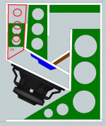
Taking advantage of this post here are some images regarding bracing, cone correction and grip.
It has enough bracer for 800W cab?
Green = Bracer
Blue = Cone correction
Brown = Grip
I'm being conservative regarding horn path, increasing it will make diaphragm displacement increase and this might be a problem for my driver. I found some better options them current one at the same cab volume but I ignored them due to the same diaphragm displacement issue. It's also not clear if I just need to adapt current path or if I need to fold and unfold again. In addition, check my post # 11, is an effect then just adapting path will bring.
Taking advantage of this post here are some images regarding bracing, cone correction and grip.
It has enough bracer for 800W cab?
Green = Bracer
Blue = Cone correction
Brown = Grip
An externally hosted image should be here but it was not working when we last tested it.
An externally hosted image should be here but it was not working when we last tested it.
An externally hosted image should be here but it was not working when we last tested it.
An externally hosted image should be here but it was not working when we last tested it.
Thanks for your suggestion Oliver.
I extended it till the baffle and add two additional small bracer between cone correction and baffle. Do you think it's necessary or too much? I already saw doubling baffle but never saw people adding bracer there (my experience is too short).
The plan is to build the cab in polywood 15mm, what thickness would you suggest to build the bracer? ? 12mm or 10mm?
An externally hosted image should be here but it was not working when we last tested it.
Hi,
I'd just use the same plywood that is used for the other panels for the braces. I like the little braces from cone-correction to driver baffle, that's an area that needs as much support as it can get, and you made the internal width a little larger than necessary, so additional support cannot hurt. Also, add a second layer just around the sides and bottom of the mouth about 2"-or so-wide, than use a removable perforated (or extruded) metal grill.
Regards,
Last edited:
- Status
- This old topic is closed. If you want to reopen this topic, contact a moderator using the "Report Post" button.
- Home
- Loudspeakers
- Subwoofers
- TH 15" flat response to 35Hz (-3dB) - By LORDSANSUI