Member
Joined 2009
Paid Member
I wonder if that Q0L box is stepping on a patent from somebody else:
Patent US8041045 - Unnatural reverberation - Google Patents
They both do something similar - take a number of samples of the signal and phase/time shift them and then add them back. It amazes me how many attempts there are to 'improve' on the sound reproduction process.
Patent US8041045 - Unnatural reverberation - Google Patents
They both do something similar - take a number of samples of the signal and phase/time shift them and then add them back. It amazes me how many attempts there are to 'improve' on the sound reproduction process.
D.Self's speaker delay has Power ON detection and delay. It has AC detect and powers OFF in one half cycle or two half cycles (by swapping resistor value) on loss of AC. It can also detect a temperature switch. It has LF filtering for DC detect.Does this mute automatically turn off again or is it reset by the power on button.
None of the go to OFF latch.
They all come back ON after the set delay on return of OK conditions.
Gareth, when you done, would you kindly show your complete finalized (as built) pre-amp schematics for those interested to build it.
Reason why I ask, when a thread becomes long it becomes increasingly difficult to find and follow the latest as built and working system especially if it is broken up among several modules like this one.
Reason why I ask, when a thread becomes long it becomes increasingly difficult to find and follow the latest as built and working system especially if it is broken up among several modules like this one.
Member
Joined 2009
Paid Member
Member
Joined 2009
Paid Member
At high frequencies the error amplifier's gain begins to roll off, and so the voltage regulator's output impedance begins to rise. A capacitor across the output has an impedance which falls when frequency rises, which is a pleasant cancellation.
I think your calculator will agree with mine: at 10 kHz, a 1.0uF capacitor's impedance (magnitude) is 15.9 ohms. Use that to scale to your target impedance at target frequency. Maybe the answer is, you want 0.0004 picofarads(?) at the regulator output. Hammer upon the keypad and find out.
I think your calculator will agree with mine: at 10 kHz, a 1.0uF capacitor's impedance (magnitude) is 15.9 ohms. Use that to scale to your target impedance at target frequency. Maybe the answer is, you want 0.0004 picofarads(?) at the regulator output. Hammer upon the keypad and find out.
Member
Joined 2009
Paid Member
The gain will roll-off, but it's doing so at very high frequencies. Why do I need to extend the low Zout at that point - it's not needed?
Think of it as a bypass route for any signals generated by the RIAA to exit stage left.
Member
Joined 2009
Paid Member
I've been thinking about it, the shunt regulator holds the rails still, with very low Zout over a very wide frequency range - any signal current flowing through the rails is gobbled up by the shunt regulator. The regulator is an 'active capacitor' as good or better than anything I can fit on the board except at frequencies well beyond the audio range. At 100kHz, the Zout of the regulator is still very low. At r.f. we have an R+C across the rails, a kind of zobel.
Last edited:
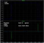
Connect an LTSPICE current source to the shunt regulator's output and have it draw a square wave of current from the regulator. Something like Ilow=5mA, Ihigh=12mA, risetime=2ns, falltime=2ns, hightime=1us, period=2us. Then plot the current which flows in the 33uF capacitor across the regulator output. The capacitor current is the amount of stress removed from the regulator. Every milliamp that flows in the capacitor is a milliamp that doesn't flow in the regulator. The capacitor's action is similar to a bulletproof vest; it absorbs and spreads out much of the impact force of the bullet, so the resulting wound is survivable rather than lethal.
Member
Joined 2009
Paid Member
I can't run a sim today. But I can imagine that the current will be shared between the shunt and cap in proportion to their impedance. The lower impedance will dominate and over a large range this is the shunt. Why do I care about some stress on the shunt, it's simply doing the job it was designed for ??
If you do run a simulation with and without the 33uF capacitor across the output, you might see results that resemble the attached image. It comes from a different shunt regulator, not yours, which uses a different error amplifier and a different voltage reference scheme than yours. But the simulation results might be similar anyway.
_
_
Attachments
Member
Joined 2009
Paid Member
I can see the blue is smoother. It says that the shunt regulator is unable to keep up with the current step demand (but it gives up very very little change in actual voltage). But if this has a rise time of ns ? the it's asking for response from the shunt regulator at extreme frequency. I can include a small rail decoupling capacitor, small enough to use something that would work well at high frequency. But isn't this academic ? where will such high frequency signals be generated ? the input to the phono amp has limited bandwidth. Why do I want to engineer the power supply to have low impedance at r.f. ?? - I know I'm being stubborn ")
I can see the blue is smoother. It says that the shunt regulator is unable to keep up with the current step demand (but it gives up very very little change in actual voltage). But if this has a rise time of ns ? the it's asking for response from the shunt regulator at extreme frequency. I can include a small rail decoupling capacitor, small enough to use something that would work well at high frequency. But isn't this academic ? where will such high frequency signals be generated ? the input to the phono amp has limited bandwidth. Why do I want to engineer the power supply to have low impedance at r.f. ?? - I know I'm being stubborn
In a domestic environment since the 1990's there has been an increasing use of new technologies such as switch mode power supplies, cell phones microprocessors, remote controls, fluorescent displays lighting etc etc.
Radio detection involves a feeding diode and a capacitor to earth. You have these elements in a transistor package with the base-emitter junction and capacitance between the base and the collector and emitter junctions - so the potential is there to create a disturbance if the circumstances are ripe.
I mentioned the use of ferrite coils by Technics in series with RIAA input stages - as far back as the 1990's at least.
I suggest you look at the Ie of the RIAA LTP under dynamic conditions to see what impact these have on your supply rails. Mark Johnson commented recently about how much these vary.
I agree with Andrew T about local decoupling capacitors for the RIAA.
Member
Joined 2009
Paid Member
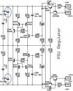
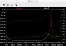
I don't mind if the shunt has to work for a living, take the stress. But I didn't like what I saw in terms of the output impedance (plotted on dB scale) peaking when the capacitance on the rail was to small. I ran a quick simulation with 1uF on the V+ rail and 10uF on the V- rail. There was obvious peaking on the V+ rail. A transient simulation with fast pulse current source produced some awkward moments. The designer has opted to keep rail caps in place 
Attachments
Last edited:
Member
Joined 2009
Paid Member
Aluminum electrolytics have a self-resonant frequency, like all other caps, but resonance looks more like a big, broad, non-resonant trough in its Z vs. F curve. IIRC, some 470µF 35V caps with cans around 7 x 15mm have self resonant frequencies around 400kHz - 600kHz, and caps with smaller cans will have SRFs around 1MHz or 2 - it's usually more of a function of the physical size of the cap, and less related to the capacitance value or voltage rating.
A small to medium valued (22µF - 470µF) high quality wet Al electrolytic will work very well to smooth a power supply rail without generating resonances of its own. If you look at the impedance plots, even above its resonance, it may have an impedance comparable to a large value monolithic ceramic cap, so it can work with an MLCC to help tame any MLCC resonances, and provide low impedance at frequencies that are too low for the relatively low capacitance MLCC to handle.
Lossy caps like aluminum electrolytics and X7R ceramics are useful on power supply rails. With X7R however, some modern parts lose a lot of capacitance when you run them at 10-20V DC bias, so check the specs or run a simulation on the manufacturer's web site first. Murata and Kemet have good simulators that let you specify DC bias and then show you the resulting specs and curves.
In general, higher voltage rated and physically larger chip X7R caps will 'squish' less with DC voltage (i.e. thicker ceramic dielectric layers squish less), but just check the site's simulation first. The difference is not subtle - some caps will have 80% of their faceplate capacitance at 17V, and some will have 20%, even though both are well within their voltage ratings. Again, the voltage induced capacitance loss is largely from the use of really thin dielectric layers, so in general, a tiny, high value X7R cap won't do much when shunting ±15V rails, even though the cap may be rated for 50V. Check the manufacturer's simulations rather than guessing.
Best of luck!
- Status
- This old topic is closed. If you want to reopen this topic, contact a moderator using the "Report Post" button.
- Home
- Source & Line
- Analog Line Level
- TGMC - a modular control pre-amplifier