http://www.diyaudio.com/forums/solid-state/54448-rega-brio-one-channel-dead.html#post5114058
Anyone who liked the NAP140 thread might like this. The Brio is based on a very simple boosted op amp called the Texan. For fun I built one on stripboard and the output stage Dead Bug. Although the thread is about repair my feeling is to make a better version is the ultimate repair. Were it not Rega I don't think I would have read it. Rega were very aware of Naim so it was their way of joing the market made by Naim.
A friend and myself need a very tough and powerful subwoofer amp. I will try to come up with a 100 watt Texan now I have mastered it's most obvious problems. All the parts from my useful junk pile.
Member
Joined 2009
Paid Member

Member
Joined 2009
Paid Member
The joy of creation.Sometimes I wonder if DiY is worth the trouble - look at what a few hundred dollars buys you. The Pioneer VSX-S520 does everything.
")
I would say if you spent a few hundred dollars you might have spent $50 and made something better. I keep things very simple and usually get a sound that is better. I set target specs and do the best power supply I can. The case should I bother is where money might be spent. I found a 0.67K/w heatsink by Fischer at less than $10. It is an ugly thing. It's at the back so it will do. It's not unusual to cost three times more.
I thought to set a competition where only NE5534/5532 allowed and these transistors. BC327/337 MPSA42/92 BD139/140 MJE340/350 TIP( 2N )2955/3055. The test would be blind against a Krell for example. Forgive me if you think that's a mountain to climb, it isn't. One little cheat is to find who makes 2955/3055 with better silicon. On-semi sort of say they do. Some marks given for the cost, it would have to be new stock if so. I would hope some people would junk the 5532 and use the BC327/37. 327/337 have some remarkable qualities and yet are often used for very simple tasks in power supplies and switching. They are very low noise and high gain. Like a BC550/560C + BD135/136 hybrid. One could bank up BD139/140 and not use the 2955/3055.
One could redo a NAD type design. I would say that's fine. If you look at how the most basic parts of a NAD are more like $10 transistor radio parts it is remarkable how good it sounds. That's because the designer was thinking very hard how overcome that. Proton who made the NAD never understood how it worked. Their better parts quality clones were very average.

I often get bored and want a simple idea to test. This was one that I quickly forgot until this TG project arrived. Don't be fooled by the simplicity. The circuit is trying to do many things. First, it is an attempt at a Niam like sound. If you look there is no push pull class AB stage. The red resistor is the smallest with this gain of transistor I found to be valid. Note, near 700 mW transistor dissipation is a bit high. I didn't mind it popping, it didn't !
This design would drive the inverting input of the NAP 140's 1K.
It will drive headphones.
It will drive RIAA circuits.
NE5532 was what was available in my useful box. I did replace the 220R with a current sink. I have a feeling this is better. MC33078 would be fine. The gain of BC337 is so high as to draw very little current from the op amp, it is very likely the 3K9 red resistor is more to have a Naim trait than reduction of high harmonics of distortion. With CCS one gets a tad more voltage swing into 30R. Anyone like to say what is correct for headphones? 1 Vrms seems prudent ( loud ? ).
The distortion mostly at preamp levels is the oscillator I am using ( RA53 + NE5532 ). Set gain as you please. The input resistors is just to say some required, check DC offset when complete.
This could make a very nice headpones out with extra duties possible or a Naim like building block for a simple design to go with NAP140 kits.
Member
Joined 2009
Paid Member
Nigel - am I right, with the op-amp in Class A and an emitter follower you are pushing distortion lower despite driving a 30ohm load? - looks simple and very effective.
I was thinking that I don't want the hassle (there are space and wiring issues) obtaining the power supply for this preamp from the power amplifier. So I'm going to follow the NAIM approach of placing the power supply in a dedicated box. I will in fact put the power supply for the power amp and the preamp in this separate box. I just ordered the chassis on ePay.
I was thinking that I don't want the hassle (there are space and wiring issues) obtaining the power supply for this preamp from the power amplifier. So I'm going to follow the NAIM approach of placing the power supply in a dedicated box. I will in fact put the power supply for the power amp and the preamp in this separate box. I just ordered the chassis on ePay.
I think Naim was mostly about making the most out of what they had as circuit chunks. A mechanical engineers thinking if you like. Engine and gearbox. Robin the service guy said they had no idea where 0V was. Somewhere up a SCAIC cable was his best guess . Taken at face value a daft statement. He knew how I think so knew I would like the complexity of the concept. One could say not the best idea made to work. Naim thought proximity of boxes and box type was a big sound quality factor. Keeping the feet of NAC 42/32 slightly loose was liked on early ones. Discovered by dealers who wanted to change boards during a demo. Finger tight suited best using the rubber foot as a grip.
My slightly more is less nasty SE output stage is like perfect cooking. The very high current gain transistor forces the op amp into it's very best distortion performance. I suspect it even aids the slewing ( NE5532 is tricky, often + to - power decoupling directly to the pins of circa 10 nF is helpful ). The residual distortion of a SE stage is mostly like that of a valve design or Naim NAC. As the circuit uses no foldback limiting it sounds OK up to clipping. It is my feeling that op amps seldom sound great into low loads that should be easy for them. I have no idea why, even NE5532 that boasts it can. Perhaps the residuals have too many high order harmonics albeit at a very low level. Perhaps in the same way we hear capacitor distortion that should be impossible. As for cooking, coffee and cocoa work well together. Add a very small amount of cocoa to make it taste like more expensive beans. Coffee in cocoa works also. It's not adding, it's balancing.
Strictly speaking the 3K9 red resistor is a step too far or does nothing. If changing to a BD139 it might help. Even so it forces a more Naim like spectrum. It can be to either rail ( not both ) and is based on what LM741 or LM324 needs. Forced to say what's best you should try it rather than being told by another. I have always thought a power amp could be made to work this way if up to 1 watt. Great for late night music.

Member
Joined 2009
Paid Member
Exactly. Jean Hiraga made a life journey on this. Self often deplores this idea although is careful not to name people. However Hiraga went to great lengths to find out why people have buying preferences. High distortion is neither good nor bad. Low distortion is neither is good nor bad. Distortions that has 5 th and 7 th harmonic is neither good nor bad. However feedback amplifiers that exposes 5 th and 7 th as their only traits are doubtful designs.
If one was to speculate. 1% THD at 90dB volume total for a system is 0 % in human terms as long as the spectrum decays at an exponetial rate. Anything else is at best no better. Mostly all other things are worse as they place a harmonic where we can hear it easilly. Out of sequence. Like bad colour bias on TV.
In the 1950's when the Quad ESL57 as now call it arived we were able to live this dream when FM at 50% modulation.
If Hiraga is right ( I suspect he is ), this is why all the things we feel are wrong are truely wrong. Think for one minute how unlikely it is that a $50 000 hi fi system can get close to this. Never is the truth. The microphone that gave you the sound kills any chance.
The intelligent listener will know when he or she did the right thing. Most engineers get confussed as the engineering is a thing of beauty in it's own right. I am as guilty of that as anyone.
If you want to go to the other world of hi fi join Tape Heads. It looks like DIY Audio. The guys there seem unable to know what we know. However ask about digital and suddenly they do know. I don't mean know what's best. They really know. Someone asked how FM relates to a digital system. Better than 16 bits in packets of imformation per second with horrible engineering problems that digital escapes from. I couldn't believe my eyes. Tape recording is not unlike digital in that encoding happens at the peaks of a 200 kHz bias frequency. It needs no playback decoding as an advantage.
Someone who is an accountant said in the past we didn't have the maths to prove designs and did it by guess work. In my view it is the other way. They kept things simple so the maths worked. He loves AEC busses. If only he knew the engineering they had. The Oxford Bus Company versions of the RT and RM were even better. Never ever laugh at the past. They often did more with much less by being educated in the round. See GWR railcar 1937 also. I hate busses, I love the engineering.
Member
Joined 2009
Paid Member
Member
Joined 2009
Paid Member
Member
Joined 2009
Paid Member
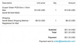
pcb's ? The tracking number shows the package arrived in Canada some time ago. I have found packages from overseas can get stuck in Canada customs for weeks - staff at Canada Post warned me the last time a letter from the UK took a day to cross the Atlantic and weeks to reach my house. Anyhow, we have a big country here, a small postal service with what must be a teeny tiny customs inspection team. I may have to re-order the pcb's but I'll wait a bit longer.
In the meantime I've decided this project needs an external power supply, independent from the power amplifier box, a power supply box just for power. I've ordered a suitable box from ePay. It too has to traverse time and space to reach me.
In the meantime I've decided this project needs an external power supply, independent from the power amplifier box, a power supply box just for power. I've ordered a suitable box from ePay. It too has to traverse time and space to reach me.
Member
Joined 2009
Paid Member
I've ordered a box. Into the box I will place two Toroidal transformers. I have them already and they will be used to provide separate L and R channel supply and grounds. The grounds will be isolated from the chassis safety earth with the usual diode disconnecting network. In the same box will be a pcb with soft-recovery discrete rectifier diodes, transformer secondary snubber networks and 63V rated capacitors. I am considering a slow-start module on the mains AC side of things. I have already designed, fabricated, built and tested the pcb rectifier board as part of my TGM1i project.
the PSU box should contain the Safety Earth connection (PE)
It should also contain the rectifiers and first stage smoothing.
The outputs of positive, zero volts and negative can be a twisted triplet.
One twisted triplet to each channel.
The Audio Ground to PE safety connection (power diodes||resistor||capacitor||bypass switch) can also be inside this box.
If you can guarantee that mains power can NEVER accidentally get onto any of the output wires, then you can consider the two twisted triplets as all you need.
If you can't guarantee that, then you must also have a PE connection (a seventh wire) between the PSU box and the receiver boxes.
- Status
- This old topic is closed. If you want to reopen this topic, contact a moderator using the "Report Post" button.
- Home
- Source & Line
- Analog Line Level
- TGMC - a modular control pre-amplifier