Member
Joined 2009
Paid Member
Well, 1W into 8R is enough to play sound through a speaker, that's really quite a strong requirement for a pre-amp, more like a power-amp. Romy-the-cat likes powerful pre-amps according to his website. Staying with Class A for 1W into 8R means pushing 0.5A through the load. With my 30V rail voltage we're talking about power-amp levels of heat-sinking which might be too much to ask from my planned chassis. I think some compromise needed here, perhaps a head-phone amp type of power level is more reasonable for a pre-amp? Say, 25mA capability in Class A with idle current up to 50mA?I have a friend who is convinced buffers should give high power. 1 watt or more. This made me think why not have 1 watt 8R
Last edited:
Member
Joined 2009
Paid Member
No, I have given up giving you advice on this project.I can't see any of it incorporated into your PCB design. Your priorities aren't the same as mine.
oh dear!
Well I did forget to look at a layout option on the regulator you suggested, let me go back and look again.
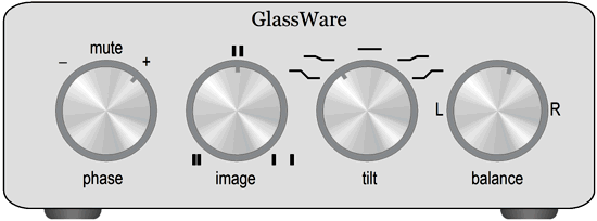
The image control (CCW=narrow, CW=wide) in #503, is in fact the "Stereo Width Expander" mentioned in #476. The $2000 QOL box only offers three discrete settings rather than the infinite adjustability of a potentiometer: (i) mono; (ii) bypass {normal stereo}; (iii) width expansion constant = 0.618 = the golden ratio. Rod Elliott gives a schematic for a continuously variable implementation. Just replace the pot with fixed resistors to get QOL.
Don't give up. I never do. I sometimes I see what I said come up later when the need says it must. It's great to be told something you said some months later. I then pretend to be suitably imformed. Often there is something new when the idea comes back.
The one thing I like about this project over all other things is the ability to back all of the horses. I suspect the author will use the simple version in the end. Although I hate tone controls I often have the need if only to say more work needed somewhere else. I wonder if they could be in the buffer if it had some gain ( gain of 1 CD, vari-gain, tone )?
That's a good point I think. If you have a source that needs tone correction add it to that source. The RIAA is so easy to change, that's a free lunch. Tuners also are 50/75 uS, that's an easy thing to add to. Tape decks also. Much as I hate CD it is the best thing to use as a reference when adjusting speaker crossover points. I hate CD much as people hate government. A gap between the promised outcome and reality.
Member
Joined 2009
Paid Member
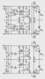
Shunt Regulator - a different option
Here's a different topology. It is a very interesting suggestion from Brian.
The key difference is the same regulator used for both +Ve and -Ve rails so we have identical behaviour in terms of Zout, step response, PSRR etc.
It also means same-sex devices, somewhat simplifying parts.
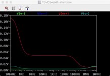
The other difference is not using a Darlington output device. Although this does nothing for simplicity of construction (same number of parts) it results in a higher Zout which is the contentious item - impact on sound. As reported earlier in the thread, Jan's magazine had an article that reported correlation between lower Zout and better sound. But not 100% and higher Zout tends to be more stable (less risk of parasitic ringing for example). The same-sex version without the Darlington has a Zout around 50mOhm, the Darlington version Zout is an order of magnitude lower in comparison. The Zout of the original version is different between +Ve and -Ve rails, but it's hard to see the difference on the attached plot because the Zout's are both very small on the scale of the plot.
Another consequence of the same-sex design is that the resistor bias for the zener reference diodes can no longer be taken to the 'opposite' rail and instead go to ground. This could simplify layout traces but it affects Zout at low frequencies, albeit only below 10Hz where we may not care.
I believe either version can be accommodated on the pcb, but not both at the same time.
Here's a different topology. It is a very interesting suggestion from Brian.
The key difference is the same regulator used for both +Ve and -Ve rails so we have identical behaviour in terms of Zout, step response, PSRR etc.
It also means same-sex devices, somewhat simplifying parts.
The other difference is not using a Darlington output device. Although this does nothing for simplicity of construction (same number of parts) it results in a higher Zout which is the contentious item - impact on sound. As reported earlier in the thread, Jan's magazine had an article that reported correlation between lower Zout and better sound. But not 100% and higher Zout tends to be more stable (less risk of parasitic ringing for example). The same-sex version without the Darlington has a Zout around 50mOhm, the Darlington version Zout is an order of magnitude lower in comparison. The Zout of the original version is different between +Ve and -Ve rails, but it's hard to see the difference on the attached plot because the Zout's are both very small on the scale of the plot.
Another consequence of the same-sex design is that the resistor bias for the zener reference diodes can no longer be taken to the 'opposite' rail and instead go to ground. This could simplify layout traces but it affects Zout at low frequencies, albeit only below 10Hz where we may not care.
I believe either version can be accommodated on the pcb, but not both at the same time.
Attachments
Last edited:
Member
Joined 2009
Paid Member
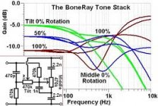
I'm looking for some 'action' in the mids, the presence region to cool off overly compressed recordings. Attached, pulled of the 'net, design is attributed to our very own Merlin.GlassWare Tilt Control
Attachments
When you run phase margin simulations to check your shunt regulator's stability, you will discover that it is ultra-stable, with gigantic margins of safety, because it contains only a single inverting amplifier stage.
{ Input --> CE --> CC --> Output } accumulates a smidgen more than 180 degrees of phase shift; however, 360 degrees of phase shift are needed for oscillation. So your circuit won't oscillate, it's far far away from the borderline of oscillation. So it's stable. Whoever told you to worry about stability, was misguided.
You can artificially boost the gain of that one amplifier stage by some fantastic multiple (1000X?) and the regulator will still be stable. Meaning you have a huge margin of safety. Try it in simulation and see.
In this topology, the circuit remains stable no matter what you do to the output impedance. You can make output impedance high, and the circuit remains stable. You can make output impedance low, and the circuit remains stable. Personally, I would make output impedance extremely low, so I wouldn't have to worry so much about the PSRR of the signal handling circuits that it powers.
Last edited:

Here's a different topology. It is a very interesting suggestion from Brian.
The key difference is the same regulator used for both +Ve and -Ve rails so we have identical behaviour in terms of Zout, step response, PSRR etc.
Why not use LM317 and LM337 with one resistor each to make a very stable and quiet constant current generator instead of two transistors and two resistors, not really very stable nor very low noise.
Member
Joined 2009
Paid Member
Nico - mostly because I like to make discrete circuits - the performance of the shunt already is very high - do you see how we could improve the discrete circuit based on the two-transistor CCS that we have ?
Mark - I was unable to make the shunt unstable in sims. What I like is that I have the option to built several versions of the shunt from the same pcb footprints. But the one thing I can't change once the copper is etched is complementary vs same-sex circuit for both +ve and -ve rails - there seems to be on balance an on-paper advantage to the latter and I only need to buy one part-type.
Mark - I was unable to make the shunt unstable in sims. What I like is that I have the option to built several versions of the shunt from the same pcb footprints. But the one thing I can't change once the copper is etched is complementary vs same-sex circuit for both +ve and -ve rails - there seems to be on balance an on-paper advantage to the latter and I only need to buy one part-type.
... and higher Zout tends to be more stable (less risk of parasitic ringing for example)
Not in the topology with Input --> CEstage --> CCstage --> Output .
Whoever told you the above, had not analyzed this particular shunt regulator.
Notice that your "same sex" design actually has no CCstage at all, in the negative half of the regulator. Whether that is worse or better, is for you and LTSPICE to decide.
Member
Joined 2009
Paid Member
Well, I've looked at the layout six-ways-to-sunday but the same-sex version is a layout headache. I exploit the symmetry of the complementary design to produce a compact layout which simply doesn't lend itself to the alternative. The layout of the +Ve and -Ve regulators in the same-sex case would be radically different which negates part of the reason. It would also take me a few hours more of effort to find a layout that worked. It's off the table. I gave it a shot.
The image control (CCW=narrow, CW=wide) in #503, is in fact the "Stereo Width Expander" mentioned in #476. The $2000 QOL box only offers three discrete settings rather than the infinite adjustability of a potentiometer: (i) mono; (ii) bypass {normal stereo}; (iii) width expansion constant = 0.618 = the golden ratio. Rod Elliott gives a schematic for a continuously variable implementation. Just replace the pot with fixed resistors to get QOL.
An early example of the concept from 1983 along with a noise blank circuit for scratches on vinyl. This is from a series of articles by the late John Linsley-Hood for a modular preamplifier - based largely on IC op.amps.
One would not have been able to build this and have it fit in a reasonable size case using discrete component modules.
Attachments
Member
Joined 2009
Paid Member
Well, I've looked at the layout six-ways-to-sunday but the same-sex version is a layout headache. I exploit the symmetry of the complementary design to produce a compact layout which simply doesn't lend itself to the alternative. The layout of the +Ve and -Ve regulators in the same-sex case would be radically different which negates part of the reason. It would also take me a few hours more of effort to find a layout that worked. It's off the table. I gave it a shot.
Maybe you could find something to fill the gap for the meantime and look for a solution without the pressure of peers waiting with expectation.
Just wondering about your input CCS pairs whether you considered splitting the 33k base resistor values R53 and R59 and stringing an electrolytic capacitor from the supply in the manner advocated by Self in his 'Blameless' designs - to steady the ship albeit to improve PSSR.
Last edited:
Well, I've looked at the layout six-ways-to-sunday but the same-sex version is a layout headache.
Which one is the same-sex version, the top or bottom schematic in post 506?
What controls the output voltage, the Zeners or something else?
Thanks.
I concur. You can just use two LM317 as they won't know which way round they are. My original suggestion to Bigun is to use LM317 series regulators rather than a shunt; using your suggestion he could use 4 LM regs in total.Why not use LM317 and LM337 with one resistor each to make a very stable and quiet constant current generator instead of two transistors and two resistors, not really very stable nor very low noise.
I do like to be interesting.Here's a different topology. It is a very interesting suggestion from Brian.
I need to point out that I did suggest the duplicate topology and the banishment of the darlingtons but in your schematic there are other components that I would not choose. The "same sex" is not the most important advice but makes more sense to me than deliberately making two different ones. You are pursuing low Zout (a functionality spec) to extreme without a clear idea why and without enough regard for other factors.
Having said that, I conclude your priority is to make a good, interesting build project rather than a high performance pre-amp. Eg: you have chosen to copy a NAD phono stage. Which is perfectly fine.
- Status
- This old topic is closed. If you want to reopen this topic, contact a moderator using the "Report Post" button.
- Home
- Source & Line
- Analog Line Level
- TGMC - a modular control pre-amplifier