Traderbaumk? S.A. spell checker?Hi Traderbaumk, I meant these buck/boost types, not the the stuff for LEDs - remember Garerth wants to drop the 45VDC to lower for the pre-amp. I know some of those Chinese switchers some are very crude, not what I meant - sorry.
Look at these things, that is what I had in mind. Followed by some caps and a linear regulator, it is dead quiet.
DC-DC Boost Buck adjustable step up down Converter XL6009 Module Solar Voltage M | eBay

Very interesting. $1.49 - how can that be made at a profit? Amazing.
That's put me in mind of amplifiers and dab radios. There are some classes of distortion that I find especially aggravating and will give me a broken glass in my ears sensation, if you will. I wonder whether you have unusual hearing or not. Perhaps your listening equipment is distorting in ways you are sensitive to.Interestingly, it was much harder than I thought. With a clean tone generator I found there wasn’t too much to be annoyed about. However, I was able, with some practice and time to sweep back and forth and focus in on areas where it was relatively less ‘nice’.
Do you find live music (unamplified) aggravates it or not?
Member
Joined 2009
Paid Member
I don't usually find live music aggravating. The exception would be electric guitar but this is when listening loud and these instruments distort a lot.
My hearing is certainly unique to me, my ears and brain will be slightly different than yours. I've read that there is a movement towards customizing the frequency response of headphones for the individual and it's even more important for in-ear phones too. It's the same with room resonances, we all have different listening rooms and it's not just low frequency EQ but all the h.f. reflections from the walls and objects around us.
The biggest and most common source of aggravation for me are amplifiers and speakers. And we see similar comments on this forum with power amplifiers having some harshness and full range single cone speakers having break-up modes. Best not to rely on a pre-amp to fix those of course. Some folk also complain about 'digital harshness' and glare in the upper treble and subjective experiences are inconsistent on this front.
Last edited:
Member
Joined 2009
Paid Member
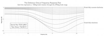
Looking at the plot from Linkwitz I see something similar to mine. He ascribed the curve to the performance of his headphone, but I'm not wondering if that's true. In my case I used headphones with built-in DSP so they will be fairly flat and just using built-in iMac speakers reproduced similar results. I've attached the plot from his website, hopefully not breaking copyright but letting it fall under 'editorial' use.
Also attached is the tone-control curves for the 'Delicious One' .
Also attached is the tone-control curves for the 'Delicious One' .
Attachments
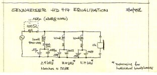
LF pole, two midband zeroes, HF pole.
Maybe you could prototype it with 3 opamps and 3 potentiometers for independent, non-interacting control of the break frequencies. Find the setting(s) that your own subjective listening deems to be the most preferable.
Ahhh, science.
Now you know exactly what you are trying to design. Implement it with all-passives, opamps, discrete devices, however you see fit.
I have also read a few interesting articles/blogs about how people go about mixing music for production. There are a number of cases where the presence region is boosted to give the music a more aggressive tone, especially so-called 'modern' recordings.
I think the annoying sound on most new recordings comes from the compression that everybody is applying deliberately. It's sad that sometimes good music is so raw and unnatural, that is practically unlistenable. Maybe that's part of your hearing issue.
Google "loudness wars". Too much compression creates amplitude distortion which is as annoying as IMD. All low level signals/harmonics are boosted to the level of the strongest ones.
What I don't understand is why artists and studios trade "good recording" for "loud recording". Is it supply and demand or people just don't care what they are listening to?!
Last edited:
Member
Joined 2009
Paid Member
Has anyone found that SMPS can not be connected -ve rail to ground? As I said before I can see why it might be prevented as part of the filtering is via class Y capacitors from DC power out to chassis+ground. Anything we might do as usual grounding will compromise the safety. As far as I can remember a capacitor to ground triggerd the protection mode. Chokes also upset the PSU. I got hum ripple which could not be removed by a linear regulator as it was in common mode I suspect ( 34mV at 50 watts, mostly 50Hz + harmonics with a little 65 kHz ). I very much doubt a common mode filter would do much at 50 Hz although my 2.3 mH sample looked not to give up at 50 Hz ( XL = <1R ). The 48V PSU adjusted to 55V seems to give a 23-32 V reading into meter high Z between DC power rails to chassis, thus the class Y caps don't act equally although equal value. I didn't try the +ve to ground as a ground connection. I am happy in this use to float the supply, I had to be more careful about the CMRR of the circuit. I fitted a RC Pi filter with both single and balanced resistors. Again no real help. What helped a little was to run the SMPS from DC ( 220 uF 500 V and rectifier ). That's a little tip I don't see given that is a logical upgrade for some SMPS.
In this project if the circuit can be run from a linear PSU do that. I wound a coil for a Raspberry Pi on the existing toroid in mintues. I did 5 turns to get a voltage reading and scealed it up. I pre measured the wire so as to make it easy. I used a LM317 type device ( LD1085/4 ) with the usual noise tweaks care of TNT Audio.
In this project if the circuit can be run from a linear PSU do that. I wound a coil for a Raspberry Pi on the existing toroid in mintues. I did 5 turns to get a voltage reading and scealed it up. I pre measured the wire so as to make it easy. I used a LM317 type device ( LD1085/4 ) with the usual noise tweaks care of TNT Audio.
mains powered SMPS are usually housed in a metal enclosure that is protected by a PE connection.
The SMPS output is usually connected to the protected enclosure.
Is this asking about that connection
The SMPS output is usually connected to the protected enclosure.
Is this asking about that connection
Has anyone found that SMPS can not be connected -ve rail to ground?
Andrew. This SMPS device I suspect is typical and for safety alone can not be taken v- to safety ground as we often do ( Raspberry Pi for example ). What I wanted to get across to people who do not find these problems in their work is don't assume throwing all you have in one box will work. With the Meanwell SMPS the ground mains wire is encouraged to the PSU box ground as it's first connection point and then the box is hard bolted to the equipement chassis to form a hard safety ground connection. If every CMRR was worth knowing about this is the prime reason I know of when SMPS noise is causing a problem.
My Panasonic TV has issues like this. It took some time to sort it out. Step one was to brake the TV RCA output grounds from the TV to the hi fi when not in use. I went on to do this for all inputs as I saw it to be a compromise we not need to have. All the pages I see written here often ignore how important what we " imagine " ground to be is. That magical lake of calm 0V reference which can be more like the North Sea.
The next fix which I have to say beat my wildest dreams was to float the TV on a 250VA 1:1 transformer which hits 253(7)VAC off load ( that's a worry when on standby ). I suspect a 230 to 115 V version would serve me well. I centre grounded that transformer output and it was bad again. This proves to me floating can work best when SMPS.
Has anyone ever updated the PW Texan amplifier? I need something to drive a motor. Sorry to hijack the thread. It is a horrible amplifier that is so close to the D Self prefered type that is looks possible to make it work better without killing the simplicity. It's crudely put a Comp feedback pair with voltage and current gain. Derek Skinner is a name that comes to mind. I said to someone I wouldn't consider it. Then I realised that was a bit daft and me being hi fi religious rather than scientific, it's only a motor. I dare say this question will interest many here in the same way as SMPS do. Something nasty than can work OK. Rega Brio1 was a version of the Texan ( Ti parts I guess? I lost my circuit dia given by Terry to do a repair, anyone have one ). That amp was a bit awful. The PSU being too small was my guess rather than just the circuit. I really like Terry the Rega designer, he admits to doing hard work to get things to work. A musician who fixed his own amps and taught himself from there. He designed an FM tuner from scratch and then DAC's! He is a very modest man who need not be.
Last edited:
Traderbaumk? S.A. spell checker?
Very interesting. $1.49 - how can that be made at a profit? Amazing.
My most humble apologies, I was eating a chocolate eclair while typing with one finger that was clean.

For us oldies what we need is an anti-loudness button. Actually, I'm not joking as much as you might think. My ears get irritated by certain frequencies, sibilance and by response peaks in speaker drivers. These unwanted artifacts occur where our ears are more sensitive. I'd actually like to consider a 'De-Ess' circuit.
This mirrors my experience with some amplifiers but not with my Nait 5i which has given several years of 'Ess' free service.
If this is a problem an actual square wave test of an amplifier into a test load with a selection of parallel capacitors should reveal what.
Smaller capacitors equate to higher resonance frequencies - in the tweeter driver pass-band - or even beyond the audible frequency range with some metal dome types.
This could upset some amplifiers - a historical snippet see The Class-A Amplifier Site - JLH Class-AB Amplifier.
Tweeter resonances can be dealt with contour networks and resonant traps in cross-over design.
I find service manuals available at Hi-Fi Engine a fruitful study. A point worth a mention is the use of ferrite beads to prevent radio spectrum rubbish from infiltrating inputs e.g.Technics RIAA amplifier stages.
Heresy perhaps but in today's digital gadget world I see sense in that move if it eliminates a problem.
The Australian Silicon Chip magazine has published a number of low distortion circuits this century and their circuits feature ferrite beads on signal inputs and some pre-amplifier outputs as well. The latest Silicon Chip power amplifier project includes a ferrite bead in the input - a first for any of their power amplifier designs.
I am reminded of the review of an Audiolab amplifier a decade or so ago where the usual input low-pass filter was not good enough to prevent rf and a second low pass with a small ceramic capacitor had to be fitted.
I have been simulating a couple of my own circuits for a new project recently - the input low pass filter is very sensitive to the signal feed - I use 10kHz square wave for that purpose.
With regard to the Naim pre-amplifier the second transistor in this has a high value collector load resistor which forces the collector voltage to be low and the collector to base capacitance to be high.
I see this as working in harmony with the operating frequency of the power amplifier.
My most humble apologies, I was eating a chocolate eclair while typing with one finger that was clean.
More silent than crunching on potato crisps.
Might want to include a Sound Field Widener like the QOL which continues to get Class-A ratings in The Absolute Sound here is their review.
It's just a couple opamps and a DPDT relay to engage/disengage the effect. (link). The technology is also discussed under the name Blumlein Shuffler.
It's just a couple opamps and a DPDT relay to engage/disengage the effect. (link). The technology is also discussed under the name Blumlein Shuffler.
Member
Joined 2009
Paid Member
I have been thinking about this, the rf-filter on the RIAA input is counter to what I'd like to put there because I'd prefer to have no capacitor on the input since it's a risk for frequency response 'peaking' with the inductive cartridge. I have some surface mount 1206 size ferrite isolators that I bought sometime ago and never used. But a ferrite inductor in series with the phono input - haven't see it before - can you post further details form the Technics manual on how they implemented this ?A point worth a mention is the use of ferrite beads to prevent radio spectrum rubbish from infiltrating inputs e.g.Technics RIAA amplifier stages.
Member
Joined 2009
Paid Member
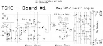
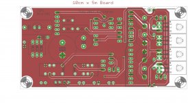
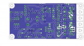
Board#1 Layout
I had a bash at a layout for the first board. It contains the phono amplifier and the source select relays. I used all over ground plane because it looks nice
It's kind of hard to see though, maybe there's a better way to show the layout than this ?
Surface mount parts on the underside, through-hole parts on the top-side. Keeps assembly simple.
This version of the phono is the combo, NAD 3020 topology is the starting point but I grafted on the output stage from the NAIM line-amp and used the better drive to reduce the impedance of the feedback network (NAD 3080 did this too).
Phono inputs on left-hand edge, isolated from everything else. Input and output signals at bottom edge. The shunt regulator supply is at the right hand side bottom edge and duplicated at the top edge for convenience.
I think I'll let this one sit for pondering.
Attachments
Last edited:
Member
Joined 2009
Paid Member
Might want to include a Sound Field Widener like the QOL which continues to get Class-A ratings in The Absolute Sound here is their review.
It's just a couple opamps and a DPDT relay to engage/disengage the effect. (link). The technology is also discussed under the name Blumlein Shuffler.
From what I can tell by reading the linked TAS review this effect is based on summing multiple copies of incrementaly phase shifted versions of the original. I believe the inspiratin for this idea is to emulate the multiple reflections generated in a room from an omnipolar source. Such sources are reported to produce a very 'spacious' sound.
I have been thinking about this, the rf-filter on the RIAA input is counter to what I'd like to put there because I'd prefer to have no capacitor on the input since it's a risk for frequency response 'peaking' with the inductive cartridge. I have some surface mount 1206 size ferrite isolators that I bought sometime ago and never used. But a ferrite inductor in series with the phono input - haven't see it before - can you post further details form the Technics manual on how they implemented this ?
From the service manual for one of my Technics amplifiers. In my DIY RIAA I simply put an FX1115 bead in series with the input. You could experiment by replacing R107 / fitting in series around a lead.
Attachments
- Status
- This old topic is closed. If you want to reopen this topic, contact a moderator using the "Report Post" button.
- Home
- Source & Line
- Analog Line Level
- TGMC - a modular control pre-amplifier