Again it is age that prevails, not experience.... Inter digital fingers where the state of the art ")
Do you remember this chip from Dallas DS1669 interestingly the wiper position is maintained with power removed. I was thinking using a momentary rotary switch with center off. Turn to the right, volume increases. Turn left volume decreases.
Returning to the series current source, any regulator chip makes a great current source using a single resistor, it is low noise and low drift.
Member
Joined 2009
Paid Member
True.Returning to the series current source, any regulator chip makes a great current source using a single resistor, it is low noise and low drift.
Obviously you need to take care about the load stability of an active CCS. Not a problem with a simple zener or JFET.
An expert at making waves? You'll fit in nicely.May I also be part of the team?
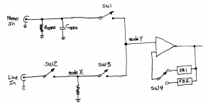
One concern about the input switch is: it requires you to route 2000 mV signals immediately adjacent to 2 mV signals. There can be "crosstalk" (signal injection) from the big strong LineIn, to the weak and tiny PhonoIn. And it's 60 dB worse (1000X) than other crosstalk situations, thanks to the disparity in signal levels.
An obvious brute force solution is: implement the switch with relays, and connect two relays in series where necessary. Then put a lot of distance between the two series relays. Shown below.
SW1-4 are the contacts of relays. To select Phono, SW1 is closed while SW2 and SW3 are both open. SW4 selects the Phono feedback network (RIAA). To select LineIn, SW1 is open while SW2 and SW3 are both closed. SW4 selects the LineIn feedback network.
The key is that SW2 (and the LineIn node) is a long loooooong way away from nodeY. When Phono is selected, there is no signal injection from LineIn to node Y. NodeX, the signal which is very close to nodeY, is quiet.
_
Attachments
Member
Joined 2009
Paid Member
Series relays - that makes good sense. However, my hair-brained all-in-one amp that looked interesting on paper will probably become a headache later so I'm going to look at a couple more options from pcb layout space perspectives. If I can put all this on the first board I'll have more options later as to what goes on other boards.
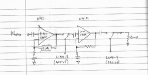
Attached scheme (phono amp based on NAD as before, cascaded into the NAIM amp) - it avoids any relay switch contacts in the phono input, the phono ground or the phono RIAA feedback path. All of which is probably much less risky.
I envisage buying or making a digital source (I'm currently without, having sold off my YBA CD player last year) and said source may become my main listening source for the CD's I ripped onto my HD and for internet streaming services that I read are becoming the most likely face of music in the future. Digital source likely won't need any gaining up but it may need a volume control so it will pipe in to 'Line-1' which also doubles as the 'passive preamp' input.
I have an FM tuner, which I like to use. The output is lower than a CD player, it'll benefit from a bit of gain and so it will pipe in to 'Line-2' the 'active' input for some modest signal gain.
And that leaves my TT along with 3 LPs (a couple of them might be double discs but one is unopened since Christmas) which is where I'll use my phono input.
Looking at this scheme I get nervous about so many capacitors, but I don't see how else to avoid nasty switching spikes if dc-levels aren't well controlled.
Attachments
Last edited:
Member
Joined 2009
Paid Member
Board#1 Layout
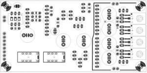
Well I do think I can squeeze the phono and gain stage on the first board. All the inputs will come to this board.
The regulator is 'partitioned off' on the right hand side. It's tight in there based on an initial go at routing this circuit. In general, impedances are kept low throughout the regulator which I think will make it less sensitive to parasitics. I'm wonder if it would be a good idea to use a top and bottom ground-plane pour. Outside of the regulator circuitry the board will contain the active signal circuitry.
To the top left are the phono inputs, clear from anything else. The phono amp occupies the left half of the board, followed by the gain stage on the right half. The main signal 'flow' is from left to right, just as you might draw the schematic. However, the output will be wrapped back over to the left hand edge of the board and kept away from the sensitive inputs.
The relays which switch the inputs and their grounds plus associated control circuitry sit at the lower edge of the board. They'll use current to/from the upstream regulator to avoid any pollution of the shunt-regulated rails and signal ground.
I'm going to put the SMD resistors on the 'underside' and the larger through-hole parts on the 'topside'.
OK - t's a bit early, I need to see if I can retain good signal integrity. And the circuit design ain't exactly stable yet. I've not sat back to think about dc-levels and switching 'thumps'; I may need another capacitor in there somewhere.
Attachments
Last edited:
Member
Joined 2009
Paid Member
Perhaps a better way to say it - with dual power rails I don't expect to use so many caps in the direct signal path - tube amplifiers are usually always single-ended power supply. All these caps add to charge-up times and potential for 'thumps' when switching plus one has to be careful to minimize possible colouration from the capacitors (I will use bipolar caps where large values are required because huge film caps are, well, huge). In tube amps, there is also the same concern, hence the attractiveness of direct coupled driver-output tube (although grid current is perhaps more to blame for that). We will use caps where they are needed!looking at tube (pre)amps and their many caps in the signal path......(and the naim preamps)......
does that make you nervous ?
Last edited:
I use a Quad FM4 and various CDP and DVd replaying CDs and find that I don't need to change the vol pot when swapping between them.I have an FM tuner, which I like to use. The output is lower than a CD player,
Most FM tuners quote the output for a 50% modulation, that is equivalent to -6dB relative to maximum.
Average levels from CDP and FM for me are similar enough to not notice.
I seem to remember similar when I used my Sugden FM tuner.
Last edited:
Member
Joined 2009
Paid Member
Perhaps that's the case for my tuner too, I only remember it subjectively being quieter than my CD player. It's an old Sansui tuner fished out of the e-waste. I wouldn't have bothered if it wasn't for free as I hadn't been listening much to FM (I sold off my Magnum Dynalab tuner already). Anyhow, I gave it a new power transformer, re-capped. Not too bad at all.
If the tuner circuit is easy to find you could look at changing it's gain. I doubt compared with the FM distortion the audio distortion would add much.
Naim used single sided 24 VDC to the preamp. This was supplied via shielded mains cable as a cheap low resistance connection ( SNAIC ). Circa 0.75mm^2. The colours being brown,blue and green/yellow. The ground was referenced to the power amp or HiCap PSU. The problem with this is no easy method of rejecting 50/60/100/120 Hz noise is available. I would expect a 20dB problem over a +/- supply. However rival company Exposure although using +/- PSU had considerable hum on an example I fixed. The problem was induction via the transformer into cables. At some point in history the ideal rotation of the transformer had been found and then lost in the production versions ( wires from the transformer are a magnetic distortion and cause this ). Although I and they could not find an ideal null point the one I found that sounded best had the 50 Hz louder than the 100 Hz on the analyser. It was possible to get a statistical minima that sounded worse ( two fixing holes, I redrilled one after narrowing the choice, it was way off ). If the amplifier box had been larger it could have been very quiet. That repair was tant's shorted rail to ground. Not unusual I am told. The owner then said it always had hum thinking it was the thing that gave up working. Not true, it hummed from the factory. I have some graphs of that. Sadly I didn't record all the datum points so useless to show here. The hum was - 75 dB at the usual volume setting before the repair ref 1 watt. One possibility was a dealer repair where the transformer was changed and the fixing was not checked. Even so someone should have known to say about it. PSU overkill with less than no advantage offered. The speakers Spendor Prelude about 90 dB/watt, really nice do anything speakers. Better than BC1's in many ways. BC3 bass unit with Audax tweeter.
What might be more interesting is I junked the Exposure preamp and built an almost identical preamp as here ( only one output buffer ). I used MC33079 op amps with gain of 1 or 2 options and passive then active RIAA, very few electrolytics used. I also junked the series LM317/337 regulators ( No2's if you don't mind the obvious ) as oscillation was found. I just used RC filters after No1 LM317/337. I had catcher zeners to limit voltage should a connection fail. In fact the RC was actually a choke with about 100R windings plus extra resistance. It measured best and was mostly doing nothing in choke terms as the 317/337 came before. It's the sort of choke we are told not to use looking like a resistor and tons of uH ( 10 000 ? ) . As it wasn't doing what it does in a purist valve design I suspect it is fine. The HF purity was noticably better, more open and sweeter. Measurements of RF noise were better. This sort of puts the low Z regulator theory in some doubt as it's the RC filter that iced that cake. To me it's about measured noise and nothing else.
That friend has a BSc in electonics and sings for a living so not given to believe hi fi folklaw. He could not find an amplifer in the shops to equal it once the design errors removed ( Another friends Krell wouldn't to my ears ). The power amp had become a Hitachi years before ( almost silent on that test ). If you study the MC33078/79 it would be hard to beat even though costing pennies, it is a simple design which helps. You could build it Dead Bug as I did. If it kills the one you plan at least you get a good sound and it should be an afternoons work. The 33079 lets you see the design come alive, Output - In + In, Power. Nothing to remember. Sling a 10 nF between power +/-.
Kinda kills the need for a 10 milliohm shunt regulator.BTW. Naim has a 27R resistor into the preamp boards to brake a PSU hum loop. It's to V+.
Member
Joined 2009
Paid Member
It doesn't take long to see why NAIM started putting regulators in most of their products, the native PSRR of several of their designs is quite poor.
OK, you gotta look at the capacitor they placed after the 27R. Think of the 27R as the CCS from a shunt regulator input and the cap as the shunt regulator. I think they used a 47uF cap. Quickly we can see that the "RC shunt regulator" is very poor over most of the audio range.
OK, you gotta look at the capacitor they placed after the 27R. Think of the 27R as the CCS from a shunt regulator input and the cap as the shunt regulator. I think they used a 47uF cap. Quickly we can see that the "RC shunt regulator" is very poor over most of the audio range.
Member
Joined 2009
Paid Member
Digital Input ?
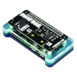
It looks to me as if it wouldn't be that hard to fit a digital input to this pre-amp. See attached image, a Pi-zero with DAC on top. May not be expensive but I read at least one review that compared it favourably to some expensive kit of just two years ago.
It looks to me as if it wouldn't be that hard to fit a digital input to this pre-amp. See attached image, a Pi-zero with DAC on top. May not be expensive but I read at least one review that compared it favourably to some expensive kit of just two years ago.
Attachments
Member
Joined 2009
Paid Member
The Dragonfly is just a USB DAC designed to plug into your laptop isn't it ?
The rpi-DAC with appropriate software is a stand-alone music server, you can stream to it over a home network, search and play music from your hardisc or connect to Spotify and even control the whole thing from your phone or ipad. That's far more attractive.
There's no budget, it's DIY, just spend it when you feel like it
It looks to me as if it wouldn't be that hard to fit a digital input to this pre-amp. See attached image, a Pi-zero with DAC on top. May not be expensive but I read at least one review that compared it favourably to some expensive kit of just two years ago.
Cool idea, I agree that an all round DAC is a better choice than the Dragonfly
What's your budget? Incorporate a Dragonfly Red? Add your own regulated supply to give the it a cleaner supply. Very compact, good sonic reputation (I haven't auditioned one).
Us old folk don't have budgets, we want it for nothing! Who cares about 24 bit if you hearing aid cant match it.
- Status
- This old topic is closed. If you want to reopen this topic, contact a moderator using the "Report Post" button.
- Home
- Source & Line
- Analog Line Level
- TGMC - a modular control pre-amplifier