Member
Joined 2009
Paid Member
... you populated the PCBs for VFA, is it just to compare with the original GB150D for a start and then you will try the CFA to re-compare?
Yes, that's the idea. I had trouble with the original VFA version and need to prove out the respun pcb first.
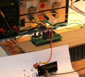
This evening I hooked it up and powered it up. With two bench supplies together I can now get up to +/-41V per rail with a regulated current-limited supply (before I could only go to +/-20V and had to use a non-current limited +/-50V supply).
It works ! .... I haven't seen any signs of instability or any oscillations at this rail voltage and with a bias of just over 100mA per rail. The zobel is cool.
R26 gets too warm for my liking and I'll likely increase the value of this resistor to lower the power dissipation in it.
Square wave looks very clean.
Listening tests confirm it's sounding good although the power supplies are a bit iffy for sound quality and the source was an iPad (MP3). To conduct proper listening tests I need to put it in a box - I'm going to buy a new box for it.
Attachments
Member
Joined 2009
Paid Member
So far I have positive impressions. But proper listening needs a proper box and power supply which will take a bit more time.
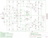
The CFA version comes later; I'm posting a build schematic for that one:
The CFA version comes later; I'm posting a build schematic for that one:
Attachments
Member
Joined 2009
Paid Member
Hi Borys, thanks for the kind words. The bias (idle current) appears to be quite well controlled. The implementation is very close to what Greg used - he had a diode-wired transistor in the CCS circuit act as a temperature sensing element (in contact with the output device), whereas I use the CCS transistors (Q1 and Q2 also in contact with the output device) to do the same job. So I essentially have the same temperature measuring sensitivity and hence it works as effectively as it does in Greg's circuit. Was this your question ?
Thanks for explenation.
The circuit for CFA VFA looks very similar so it would be easy enough to make one universal board. I tryed the Gregs amp in spice and it looks that input stage is running with bit low biasing (around 450uA for 100mA at output stage). If changed tail resistors (3,3k in Gregs amp) in the input stage for 2.2k or 1k the input bias will increase.
The question --> the 450uA bias is it enough to run input stage ??
Member
Joined 2009
Paid Member
The question --> the 450uA bias is it enough to run input stage ??
That's an excellent question - I don't know the answer as I've not enough experience. But these are my thoughts: the input stage doesn't have to drive a heavy load. It drives current into the base of the driver stage and the comp capacitors CD1&2 (BY THE WAY, for the CFA version I think these comp caps might be reduced). Since the driver is an emitter follower the LTP is not having to deal with the challenges of Miller capacitance. Hence, the slew rate of both the VFA and CFA is quite good.
In simulations I find that even at 20 kHz the current being demanded of the input pair is small (<50uA) compared with around 0.5mA of idle current. Is it enough - don't know. It can be increased as you say - I would have to check that the temperature compensation is OK with different resistor values in the input stage and CCS too.
NOTE: I found that R26, which sets the current through the drivers, gets too hot for my liking. Instead of 10k I would plan to use 18k to reduce dissipation. According to simulations the 10k dissipates 0.9W and the 2W part I selected should be fine. However, you might want to use a higher value here to reduce the temperature of the resistor although this may require the feedback compensation to be adjusted for best sq. wave as less current through R26 affects the current drive to the FET gates.
Last edited:
CFA ....
Hi Bigun
You finally came along with the CFA version implementation")
As you already know I am quite interested in this version...
Ensure to have sufficient power for the R21/R23 feedback resistors and select low temp coefficient too. The power supply should be very big to compensate the lower PSRR...
Keep us posted
Fab
?....
The CFA version comes later; I'm posting a build schematic for that one:
Hi Bigun
You finally came along with the CFA version implementation
As you already know I am quite interested in this version...
Ensure to have sufficient power for the R21/R23 feedback resistors and select low temp coefficient too. The power supply should be very big to compensate the lower PSRR...
Keep us posted
Fab
Member
Joined 2009
Paid Member
Hey Fab - indeed I feel the lure of the CFA... you are partly to 'blame'
Good question: the feedback resistors will only see 1/4W when driven hard but I did put in pads for larger 2512 sized resistors which means 1W rated parts are readily available. Unfortunately, whilst I would have used through-hole, I could only accommodate SMT in this version of the layout.
The power supply is the reason why I'm going to be a bit slow on this.
I see 3 options for the power supply:
a) Linear power supply using some ideas I have related to use of chokes to make a quiet supply
b) A run-of-the-mill linear supply with an active regulator. I have a simulation of a regulator that floats on the d.c. but acts as a 'ripple eater' for the a.c. and incorporates a Rush Cascode
c) An SMPS power supply with supplementary filtering
They all look suitable approaches with pro's and con's. What are your thoughts ?
Last edited:
Hey Fab - indeed I feel the lure of the CFA... you are partly to 'blame'
Good question: the feedback resistors will only see 1/4W when driven hard but I did put in pads for larger 2512 sized resistors which means 1W rated parts are readily available. Unfortunately, whilst I would have used through-hole, I could only accommodate SMT in this version of the layout.
The power supply is the reason why I'm going to be a bit slow on this.
I see 3 options for the power supply:
a) Linear power supply using some ideas I have related to use of chokes to make a quiet supply
b) A run-of-the-mill linear supply with an active regulator. I have a simulation of a regulator that floats on the d.c. but acts as a 'ripple eater' for the a.c. and incorporates a Rush Cascode
c) An SMPS power supply with supplementary filtering
They all look suitable approaches with pro's and con's. What are your thoughts ?
Hi Bigun
With 40vac of signal That should give more than 1/2 w for each feedback resistor...I always try to have a lot of margin on the sensitive feedback resistor. I believe some even use Caddock resistor
which I have ever used though...
For the Power Supply each option have merits but it all depends on the implementation of course. I would first use a regular big supply ( chokes sure could help) to demonstrate the frequency and temperature stability and then move to fancy supply if required for sound appreciation.
Thanks
Fab
Member
Joined 2009
Paid Member
I have done a bit of investigation as to what I can achieve ('on paper') with a passive supply (using chokes) and I'm quite pleased with what I found so this does look viable for the CFA version. It may not be as good (on paper) as an active approach. Of course big caps and a couple of chokes take up a fair space in the box.
I'm not sure what kind of dc-speaker protection to use. I have a module I can place between the output and the speaker which is a solid state relay based circuit that I have used before. Another option is to detect and cut-off the power rails, then we have nothing between the amp and the speakers. Or, we could decide that this amp is very robust, the zener diodes on the gates will prevent over-current and all we need is a crow-bar across the power supply - which way would you go ??
I'm not sure what kind of dc-speaker protection to use. I have a module I can place between the output and the speaker which is a solid state relay based circuit that I have used before. Another option is to detect and cut-off the power rails, then we have nothing between the amp and the speakers. Or, we could decide that this amp is very robust, the zener diodes on the gates will prevent over-current and all we need is a crow-bar across the power supply - which way would you go ??
Bigun
Maybe you can try values as bellow for symulation pssr, looks bit better. My board is on the way too but it will be bit different (just cosmetics ).
I have small question about 47u cap in the feedback --> the value is bit low, in symulation gain at low frequency is bit low, when use higher value low esr capacitor the gain is getting right stright away, so it would be better to use 470uF ?
Attachments
Last edited:
Member
Joined 2009
Paid Member
Hi Borys,
For the VFA TGM7 (closest to original SKA) I don't have a concern over the PSRR. It is only with the CFA TGM7. So, if your boards are SKA boards you don't have an issue. If your boards are from Jim's Audio then you should be aware that Greg didn't authorize them and I will not support any work on those boards.
I did quite a bit of simulation regarding PSRR on this topology. I remember giving the CCS their own power supply to simulate perfect isolation from the main rails and this showed me that there isn't much point making the CCSs much better than they are now. The PSRR is then limited by the topology - the output stage of the amplifier is the VAS and so the small signal drive to the VAS from the front end is referenced to the power rails. This places a fundamental limit on what can be achieved in terms of PSRR. You can do some tricks whereby you feedback some power rail ripply to the front end and try to actively cancel it out - kind of like the Aikido amplifier or Loftin-White concepts and Greg may have found a way to do this with further modifications (they are not available to the public). I have no plan to further fiddle with the circuit - if the PSRR is too low then the power supply has to get better.
I tried the simulation variations along the lines of what you posted some time ago and was able to get better PSRR as you show. However, I found that there are some tradeoffs, you can improve the PSRR of one rail but affect the PSRR for common-rail noise (i.e. both rails together) or you can affect other factors like turn-on so as you explore you will need to look for unintended consequences of any changes.
The feedback cap probably should be larger, I agree. However, my initial goal was to follow Greg's design and he had a reason for every part choice. For the CFA version I do use larger valued feedback caps.
Last edited:
Hi Bigun,
I had finally the time (cold sick leave...) for reading all the threads about SKA GB 150 and TGM7.
I like those amplifiers very much and appreciate a lot your efforts (and GB IP of course).
I my mind there is a beautiful simplicity in them.
So what about a single pair output, as you hinted at the beginning?
I am *SO SURE* It will sound better. No current sharing, no unbalances, less distorsion. And you won't need a TO126 as a "washer".
I' m thinking to something appropriate.
Hopefully somebody still Designs MOS for linear (I mean analog) applications.
I like a lot those IXYS LINEAR L2 MOSFET
They have a special construction for avoiding hot sposts (alike secondary breakdown) and this results in an improved SOA for DC use (I am thinking to open another thread about a specific monster OP with them) .
The input capacitance is huge, but it should be manageable.
What do you think?
BTW do you plan to make your PCBs available to us for a reasonable price?
I had finally the time (cold sick leave...) for reading all the threads about SKA GB 150 and TGM7.
I like those amplifiers very much and appreciate a lot your efforts (and GB IP of course).
I my mind there is a beautiful simplicity in them.
So what about a single pair output, as you hinted at the beginning?
I am *SO SURE*
It will sound better. No current sharing, no unbalances, less distorsion. And you won't need a TO126 as a "washer".I' m thinking to something appropriate.
Hopefully somebody still Designs MOS for linear (I mean analog) applications.
I like a lot those IXYS LINEAR L2 MOSFET
They have a special construction for avoiding hot sposts (alike secondary breakdown) and this results in an improved SOA for DC use (I am thinking to open another thread about a specific monster OP with them) .
The input capacitance is huge, but it should be manageable.
What do you think?
BTW do you plan to make your PCBs available to us for a reasonable price?
Last edited:
Member
Joined 2009
Paid Member
Hi Effebi,
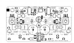
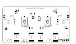
Those look like very sturdy MOSFETs. Well, you can easily use only a single pair with my pcb, just populate the outer positions only. Your MOSFET looks to have the right kind of gate threshold voltage to work in this circuit. The large gate capacitance is not something I've worked with before and it might roll off the open loop gain a little earlier but I wouldn't expect it to impinge on the good sound.
I'm willing to make my pcb's available if there is interest. The design is different from Greg's and so does not infringe on his copyright. I have sent a few boards to people already and for the last pair I sent to Canada I received $20 including postage. I'm not interested in making a business out of this, only to cover my costs and if there's money left over I'd like to upgrade my Freeware version of Eagle pcb layout license to a license that will allow me to design bigger boards with more layers for future projects.
Member
Joined 2009
Paid Member
Hi Borys,
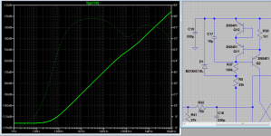
I'm on travel right now (Texas today, LA tomorrow) so I can't do anything for awhile. But I'm not surprised by what you have found. I think I asked Greg this question awhile back - what I asked him was why does he use a zobel for common source output when I always thought that the zobel was only needed with emitter/source follower outputs. He said it was a part of the compensation for the amplifier and was needed for stability.
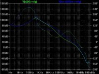
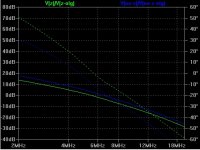
I ran a quick simulation of the Open Loop Gain of the TGM7 with zobel (Z) and without zobel (no-Z), as attached and a close up where the gain crosses 0dB. Solid lines are the open loop gains and dotted lines the phase. When the solid line crosses the 0dB line the dotted line should be above zero degrees (because at low frequencies it is at 180 degrees), in fact it is a often quoted design guideline that the phase needs to be around 60 degrees above for good stability. It shows that the stability margin is reduced without the zobel network. Trouble with simulation is there are no parastics, especially from the pcb - but that's all I can do for you for now...
I'm on travel right now (Texas today, LA tomorrow) so I can't do anything for awhile. But I'm not surprised by what you have found. I think I asked Greg this question awhile back - what I asked him was why does he use a zobel for common source output when I always thought that the zobel was only needed with emitter/source follower outputs. He said it was a part of the compensation for the amplifier and was needed for stability.
I ran a quick simulation of the Open Loop Gain of the TGM7 with zobel (Z) and without zobel (no-Z), as attached and a close up where the gain crosses 0dB. Solid lines are the open loop gains and dotted lines the phase. When the solid line crosses the 0dB line the dotted line should be above zero degrees (because at low frequencies it is at 180 degrees), in fact it is a often quoted design guideline that the phase needs to be around 60 degrees above for good stability. It shows that the stability margin is reduced without the zobel network. Trouble with simulation is there are no parastics, especially from the pcb - but that's all I can do for you for now...
Attachments
Last edited:
Hi Borys,
I'm on travel right now (Texas today, LA tomorrow) so I can't do anything for awhile. But I'm not surprised by what you have found. I think I asked Greg this question awhile back - what I asked him was why does he use a zobel for common source output when I always thought that the zobel was only needed with emitter/source follower outputs. He said it was a part of the compensation for the amplifier and was needed for stability.
I ran a quick simulation of the Open Loop Gain of the TGM7 with zobel (Z) and without zobel (no-Z), as attached and a close up where the gain crosses 0dB. It shows that the stability margin is reduced without the zobel network. Trouble with simulation is there are no parastics, especially from the pcb - but that's all I can do for you for now...
Whatever would be added p2p for now. Just keep track.
Regards
Hi Bigun,
Hopefully somebody still Designs MOS for linear (I mean analog) applications.
I like a lot those IXYS LINEAR L2 MOSFET
They have a special construction for avoiding hot sposts (alike secondary breakdown) and this results in an improved SOA for DC use (I am thinking to open another thread about a specific monster OP with them) .
The input capacitance is huge, but it should be manageable.
What do you think?
The IXYS Mosfets are only N-channel, what about the P-channel types, required for the SKAs?
- Home
- Amplifiers
- Solid State
- TGM7 - an amplifier based on Greg Ball SKA