Bigun thanks.
Looks likte zobel in this case is really needed. I have spend nearly 2 hours to get my board stable, the zobel is ice cold anyway and amp is very stable with it (even 20kHz swquare + 0.47uF looks really ok). But without zobel network amp is going mad at approx 5 - 9MHz depending on the feedback cap and input transistor biasing. I have to prepare pcb v2 anyway.
Looks likte zobel in this case is really needed. I have spend nearly 2 hours to get my board stable, the zobel is ice cold anyway and amp is very stable with it (even 20kHz swquare + 0.47uF looks really ok). But without zobel network amp is going mad at approx 5 - 9MHz depending on the feedback cap and input transistor biasing. I have to prepare pcb v2 anyway.
Member
Joined 2009
Paid Member
Member
Joined 2009
Paid Member
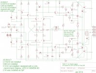
As Built Schematic
Here's the VFA only schematic as built so far (for the gentlemen in Germany who has two pcb's on the mail....)
I didn't try to fine tune the compensation capacitors (C14, CD1, CD2, CZ1,2,3&4) - I was just happy that there were no signs of any oscillations
For C14 I didn't want to use an SMT part because it's difficult to get a pair of soldering irons in there to remove it again (due to surrounding components) so I decided to tack a through-hole part instead. I didn't have one of the right value (around 6pF) so I used two 10pF parts in series (=5pF).
I didn't install the SMT bypass caps for the rail filter caps (C17 & C18) due to not having any to hand. I don't think they are necessary, or will add any value and recommend they not be installed in case of any unintended consequences.
The one thing I didn't like was how warm R26 gets - this is the emitter load resistor for the emitter follower drivers. It operates within it's rated power dissipation including a reasonable amount of de-rating but it gets pretty warm. If I had the parts to hand I'd swap it out for something around 18k (instead of 10k). This change will reduce the current available for the FET gates but simulations say this won't be an issue and I plan to make that change when I have the parts to do so.
I installed a link instead of an input cap. I wasn't planning to use one and only added the footprint at the last minute. There are two footprints, one for a small cap (recommend: Digikey UES1V100MEM-ND ) or a larger one where it will sit on top of an SMT resistor (for that I have some nice 100uF bipolars used in TGM8).
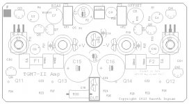
It's a small board, not that beginner friendly - you have to install all the SMT parts first. The TO-126 devices that solder to the underside have to be carefully positioned to line up with the pcb mounting holes. This is a bit fiddly and it's worth taking some time to do it well. The dummy TO-126 parts used as washers for the two middle holes are the most fiddly bit to align - take care to ensure their central metal tabs aren't bent down too far so that they can't lie flat against the pcb surface. Once you get them installed it's plain sailing. For the power MOSFETs, they should be installed last by bending their legs, install them without soldering and bolt the whole assembly to the heatsink. This will hold them all flat - then you solder their leads from the topside. This ensures their back surfaces are all co-planar and will mount nicely against the heatsink for cooling (remember to go back and insert insulated pads)
I found it useful to print out the silk screen images (post 164) and shade in the parts as they are installed. I've reposted the top silk screen again here as some parts values were obscured in the earlier diagram.
Here's the VFA only schematic as built so far (for the gentlemen in Germany who has two pcb's on the mail....)
I didn't try to fine tune the compensation capacitors (C14, CD1, CD2, CZ1,2,3&4) - I was just happy that there were no signs of any oscillations
For C14 I didn't want to use an SMT part because it's difficult to get a pair of soldering irons in there to remove it again (due to surrounding components) so I decided to tack a through-hole part instead. I didn't have one of the right value (around 6pF) so I used two 10pF parts in series (=5pF).
I didn't install the SMT bypass caps for the rail filter caps (C17 & C18) due to not having any to hand. I don't think they are necessary, or will add any value and recommend they not be installed in case of any unintended consequences.
The one thing I didn't like was how warm R26 gets - this is the emitter load resistor for the emitter follower drivers. It operates within it's rated power dissipation including a reasonable amount of de-rating but it gets pretty warm. If I had the parts to hand I'd swap it out for something around 18k (instead of 10k). This change will reduce the current available for the FET gates but simulations say this won't be an issue and I plan to make that change when I have the parts to do so.
I installed a link instead of an input cap. I wasn't planning to use one and only added the footprint at the last minute. There are two footprints, one for a small cap (recommend: Digikey UES1V100MEM-ND ) or a larger one where it will sit on top of an SMT resistor (for that I have some nice 100uF bipolars used in TGM8).
It's a small board, not that beginner friendly - you have to install all the SMT parts first. The TO-126 devices that solder to the underside have to be carefully positioned to line up with the pcb mounting holes. This is a bit fiddly and it's worth taking some time to do it well. The dummy TO-126 parts used as washers for the two middle holes are the most fiddly bit to align - take care to ensure their central metal tabs aren't bent down too far so that they can't lie flat against the pcb surface. Once you get them installed it's plain sailing. For the power MOSFETs, they should be installed last by bending their legs, install them without soldering and bolt the whole assembly to the heatsink. This will hold them all flat - then you solder their leads from the topside. This ensures their back surfaces are all co-planar and will mount nicely against the heatsink for cooling (remember to go back and insert insulated pads)
I found it useful to print out the silk screen images (post 164) and shade in the parts as they are installed. I've reposted the top silk screen again here as some parts values were obscured in the earlier diagram.
Attachments
Last edited:
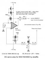
Hi PauloPT, would it be difficult to include the dc servo, instead of the NFB cap, in the TGM7 or SKA150 and can you show us the dc servo circuit that could be used instead of the NFB cap... thanksI hate SMDs...
A sugestion: design a dc servo instead of the NFB cap. DC coupled the amp sounds fabulous!

Hi PauloPT, would it be difficult to include the dc servo, instead of the NFB cap, in the TGM7 or SKA150 and can you show us the dc servo circuit that could be used instead of the NFB cap... thanks
Hi PingPing,
See the attached pic. This was posted long ago in an SKA thread but I can't find it. Luckily I had downloaded the pic at the time.
I have a BlackGate FK in the NFB and it sounds pretty good. But, with the amp DC coupled there is more detail, more bass extension and the music notes have a more prolonged decay. I note this particularly with piano notes.
It's not a night and day difference but that extra refinement is there.
Please do not try to DC couple the amp without a servo. You could damage your speakers!
Greg has a servo kit made for the SKA, you may want to drop a visit at his site - SKA sponsored Audio Forum - Products.
Good luck with your build!
Attachments
Last edited:
Member
Joined 2009
Paid Member
Member
Joined 2009
Paid Member
Member
Joined 2009
Paid Member
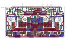
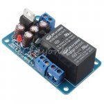
I decided to add a dc-protection module for the speaker. I also didn't want to bother making my own this time (TGM8 has an integral protection circuit on-board) so I thought I'd try one of the wonder boards off eBay.
It was $5 including shipping. I can't buy anything from Digikey for that - the shipping alone is $8!
It's a stereo board and I'll use it for only one channel. I'll wire the relays in series as this gives extra protection from prolonged arcing across contacts caused by inductive loads. As we all should know, low cost relays will likely fail to protect a speaker when additional precautions are not taken. I checked the pcb layout - the relays are set up to switch the load to ground in case of a fault which is another key requirement - encourages any arcing to shunt to ground. I may wire a capacitor across the contacts of one of the relays as extra protection against arcing.
It comes as a kit, yet to be assembled. I'm quite interested to see what $5 buys me.
Attachments
Last edited:
Wiring the relays in series will probably not help much, if at all.
Adding a cap across the opening contacts will not help quench a DC current arc across the opening contacts
Note the DC rating of the contacts:
10A @ 25Vdc. or is it 28Vdc?
This limits this relay to supply rails below +-25Vdc.
Most relays cannot do better.
Are you sure the NC contact is connected to Speaker Ground?
It should be possible to add a connection to achieve this.
It might be worth looking to add a resistor from NC to Speaker Ground.
Irrespective of all that it is a worthwhile precaution to add DC detection and speaker isolation.
This will work for low level DC errors upto the relay limit.
Last edited:
I bought a couple of those. Using one in my SKA GB150. Seems to work fine though I haven't had a situation where the amp tested it. I will have to test to see if it shunts the speaker to ground. My recollection is that it opens the circuit. I have one on the shelf that I can test. One thing I do remember is that it doesn't like over voltage from the transformer. Keep it between 12 and 15v.15v might even be too high.
Member
Joined 2009
Paid Member
Wiring the relays in series will probably not help much, if at all.
You might be right, but I remember reading a couple of times now that doing this lengthens the possible air-gap that increases the sustaining voltage for arcs. And with two contacts trying to move the arc to GND perhaps it improves the robustness of the system under fault.
- Home
- Amplifiers
- Solid State
- TGM7 - an amplifier based on Greg Ball SKA